
TM 55-2815-574-24
0032
INSTALLATION - Continued
(Figure 19, Item 4)
Figure 22. Lifting Brackets.
8.
Perform engine alignment check (TM 55-1925-205-23).
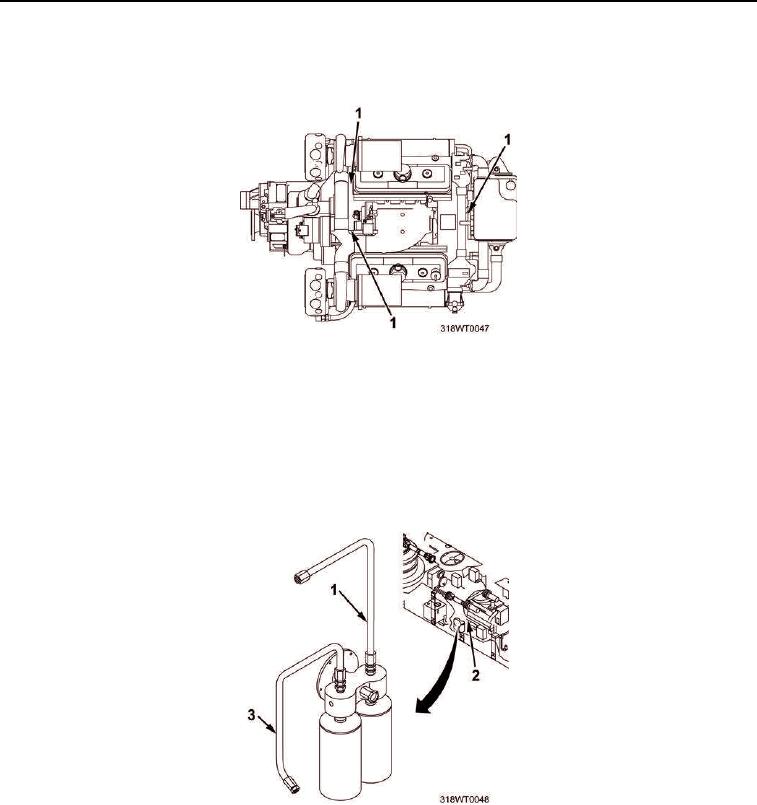
9.
Remove twine securing oil filter supply line (Figure 23, Item 1) and oil filter return line (Figure 23, Item 3)
outboard.
10.
Connect oil filter supply line (Figure 23, Item 1) and oil filter return line (Figure 23, Item 3) to engine oil
cooler (Figure 23, Item 2).
Figure 23. Oil Filter Supply/Return Lines Installation.
11.
Remove twine securing raw water return hose (Figure 24, Item 1).
12.
Position two hose clamps (Figure 24, Item 3) securing raw water return hose (Figure 24, Item 1) to marine
gear cooler coupling (Figure 24, Item 2) and tighten hose clamps (Figure 24, Item 3).