
TM 55-2815-574-24
0099
ADJUSTMENT - Continued
NOTE
It may be necessary to upset the actuator lever to cause oscillation.
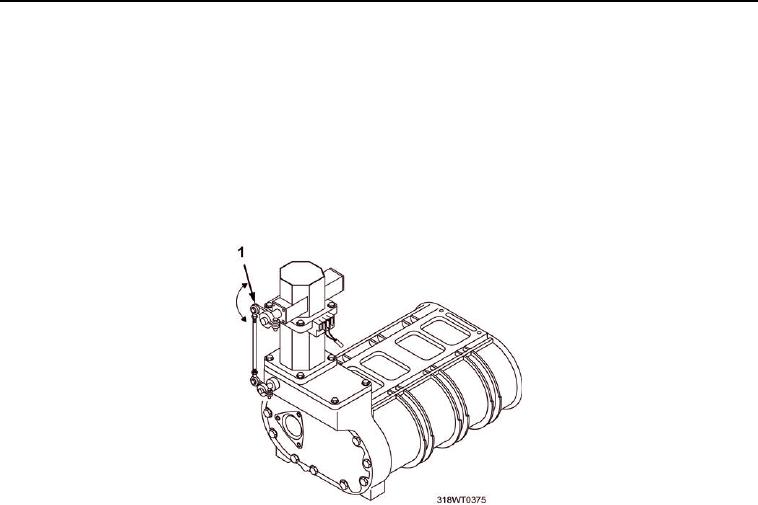
f.
Turn the S1 setting clockwise slowly until the actuator lever (Figure 4, Item 1) becomes unstable and
oscillates slowly.
g.
Turn the S1 potentiometers slowly counterclockwise until the actuator lever (Figure 4, Item 1) is stable.
h.
Disturb the actuator lever (Figure 4, Item 1) and verify that it oscillates three to five times, getting
slower and slower.
Figure 4. Actuator Lever.
i.
Operate vessel and verify that the load-to-performance change is satisfactory.
6.
Shut engine down (TM 55-1925-205-10).
7.
Close cover (Figure 5, Item 3), of enclosure (Figure 5, Item 2) rotate six clamps (Figure 5, Item 1), and
secure with six screws (Figure 5, Item 4).
8.
Remove LO/TO from A3 breaker switch. Refer to FM 4-01.502 for LO/TO procedure.

