
TM 55-2815-574-24
FIELD MAINTENANCE
ENGINE
ELECTRONIC GOVERNOR CONTROLLER REPLACEMENT
INITIAL SETUP:
Tools and Special Tools
Personnel Required
General mechanic's tool kit
Engineer 88L
(WP 0179, Table 1, Item 130)
Chemical gloves (WP 0179, Table 1, Item 52)
References
Industrial goggles (WP 0179, Table 1, Item 54)
FM 4-01.502
TM 55-1925-205-10
Materials/Parts
Antiseize compound (WP 0178, Table 1, Item 6)
Equipment Condition
Marker tags, with metal eyelet patch Qty: 2
Heat exchanger cool to touch
(WP 0178, Table 1, Item 36)
Propulsion module ventilated
Tiedown strap Qty: AR
(TM 55-1925-205-23)
(WP 0178, Table 1, Item 35)
REMOVAL
WARNING
Remove all jewelry before conducting maintenance. Do not wear watches, rings,
identification tags, or other jewelry which could short across electrical components or catch
on vehicle components. Failure to comply may result in personnel injury or death.
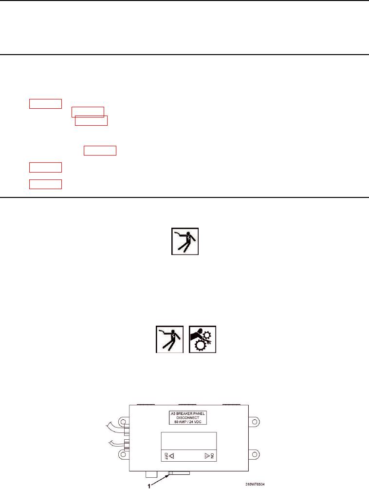
1.
Place A3 breaker switch (Figure 1, Item 1), located on A10 panel, in OFF position. Refer to
TM 55192520510 for breaker location.
WARNING
Before attempting any maintenance, ensure power supply (switches, circuit breakers, etc.)
has been disconnected and locked/tagged out against unauthorized accidental start-up or
else death or serious injury due to electric shock and/or moving machinery could occur.
2.
Lock Out/Tag Out (LO/TO) A3 breaker switch (Figure 1, Item 1). Refer to FM 4-01.502 for LO/TO procedure.
Figure 1. A3 Breaker Switch.