
TM 55-2815-574-24
0098
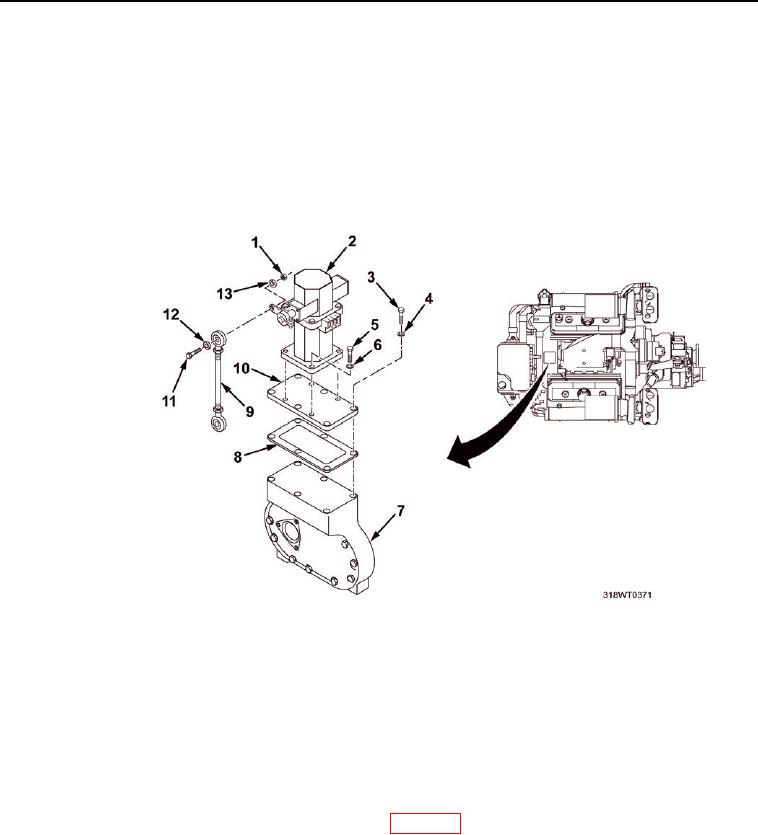
INSTALLATION - Continued
5.
Install four key socket head screws (Figure 3, Item 5) and lockwashers (Figure 3, Item 6) to secure governor actuator
(Figure 3, Item 2) to adapter plate (Figure 3, Item 10).
6.
Tighten key socket head screws (Figure 3, Item 5).
7. Connect linkage (Figure 3, Item 9) to governor actuator (Figure 3, Item 2) and install
hex head bolt (Figure 3, Item 11), flat washer (Figure 3, Item 12), lockwasher (Figure 3, Item 13), and
hex nut (Figure 3, Item 1).
8.
Tighten nut (Figure 3, Item 1).
Figure 3. Governor Actuator.
9.
Connect two wires (Figure 2, Item 2) as tagged, to back of electronic governor actuator (Figure 2, Item 1)
and remove tags.
10.
Remove LO/TO from A3 breaker switch. Refer to FM 4-01.502 for LO/TO procedure.
END OF TASK
FOLLOW-ON MAINTENANCE
1.
Adjust engine electronic governor controller (WP 0099).
2.
Perform operational check of diesel engine (TM 55-1925-205-10).
END OF TASK
END OF WORK PACKAGE
0098-4