
TM 55-2815-574-24
0098
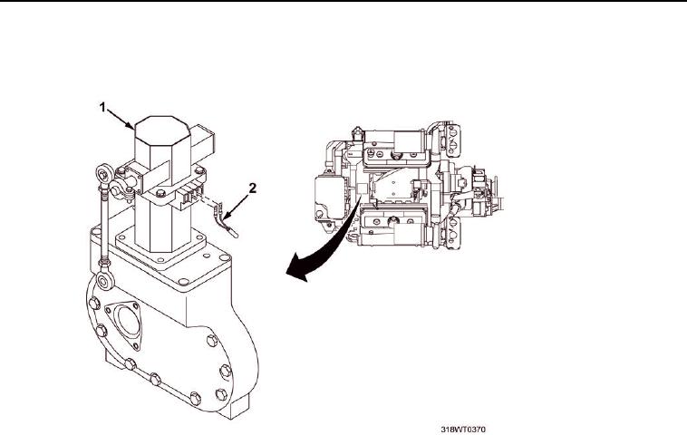
REMOVAL - Continued
3.
Tag and disconnect two wires (Figure 2, Item 2) from back of electronic governor actuator
(Figure 2, Item 1).
Figure 2. Electronic Governor Actuator.
4.
Remove hex head bolt (Figure 3, Item 11), flat washer (Figure 3, Item 12),
lockwasher (Figure 3, Item 13), and hex nut (Figure 3, Item 1) from linkage (Figure 3, Item 9) and
disconnect linkage (Figure 3, Item 9) from governor actuator (Figure 3, Item 2).
5.
Remove four key socket head screws (Figure 3, Item 5) and lockwashers (Figure 3, Item 6) from
governor actuator (Figure 3, Item 2).
6.
Remove governor actuator (Figure 3, Item 2) from adapter plate (Figure 3, Item 10). Discard
governor actuator.
7.
Remove six bolts (Figure 3, Item 3) and lockwashers (Figure 3, Item 4) securing
adapter plate (Figure 3, Item 10) to blower housing end plate (Figure 3, Item 7).
8.
Remove adapter plate (Figure 3, Item 10) and gasket (Figure 3, Item 8). Discard
gasket (Figure 3, Item 8).
END OF TASK
INSTALLATION
1.
Position new gasket (Figure 3, Item 8) and adapter plate (Figure 3, Item 10) on
blower housing end plate (Figure 3, Item 7).
2.
Install six bolts (Figure 3, Item 3) and lockwashers (Figure 3, Item 4) to secure
adapter plate (Figure 3, Item 10) to blower housing (Figure 3, Item 7).
3.
Tighten bolts (Figure 3, Item 3).
4.
Position new governor actuator (Figure 3, Item 2) on adapter plate (Figure 3, Item 10).