
TM 55-2815-574-24
0061
INSTALLATION - Continued
3.
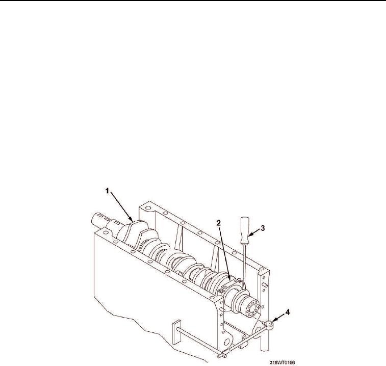
Check the crankshaft (Figure 7, Item 1) end play.
a.
Attach the dial indicator (Figure 7, Item 4) guide rod to the block, and attach the dial indicator to the
guide rod so that it is positioned on the end of the crankshaft (Figure 7, Item 1).
NOTE
With new parts, the end play should be 0.004 to 0.011 in.
(0.01016 to 0.02794 cm).
With old parts, the end play should not be more than 0.018 in. (0.04572 cm).
b.
Use a small 12 in. pry bar to keep a constant pressure on the crankshaft (Figure 7, Item 1) toward the
gauge and set the dial indicator to zero.
c.
Place the pry bar on the other side of the bearing cap (Figure 7, Item 2) and pry the crankshaft
(Figure 7, Item 1) in the opposite direction.
d.
Read the dial indicator.
Figure 7. Crankshaft End Play.
e.
If the end play is insufficient, proceed as follows:
(1)
Check for misaligned rear main bearing (Figure 8, Items 6 and 8).
(2)
Check for dirt between the crankshaft (Figure 8, Item 7), thrust washers (Figure 8, Items 4 and 9)
and the engine block (Figure 8, Item 11).
(3)
Check for burrs between the crankshaft (Figure 8, Item 7), thrust washers (Figure 8, Items 4 and
9) and the engine block (Figure 8, Item 11).
(4)
Replace thrust washers (Figure 8, Items 4 and 9).
f.
If the end play is too great, an oversize thrust washer will be required.