
TM 55-2815-574-24
0061
INSTALLATION - Continued
4.
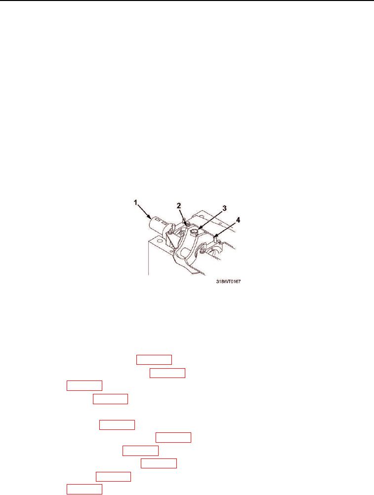
Check the crankshaft (Figure 9, Item 1) distortion.
a.
Rotate the crankshaft (Figure 9, Item 1) clockwise until the counter weights (Figure 9, Item 2) at the
rear connecting rod journal are rotated to the bottom of the engine (six o-clock position).
b.
Center punch a dimple on the inside face of each counter weight (Figure 9, Item 2), 1/4 of an inch in
and centered.
c.
Install strain gauge in the center punch holes.
NOTE
The maximum allowable variation is 0.0045 in. total indicator reading.
If the reading is greater than 0.0045 in., check the reduction gear or the
marine gear for proper alignment.
d.
Set the dial indicator to zero and rotate the crankshaft approximately 90 in each direction.
e.
Remove tool used to rotate the engine.
5.
Recheck crankshaft (Figure 9, Item 1) distortion.
Figure 9. Checking Crankshaft Distortion.
END OF TASK
FOLLOW-ON MAINTENANCE
1.
Install lube oil pressure relief valve (WP 0125).
2.
Install lube oil pressure regulator valve (WP 0123).
3.
Install oil pan (WP 0127).
4.
Install cylinder heads (WP 0047).
5.
Install vibration dampener .
6.
Install flywheel housing (WP 0072).
7.
Install fuel injector control tube and lever (WP 0086).
8.
Install port thermostat housing (WP 0141).
9.
Install starboard thermostat housing (WP 0140).
10.
Install heat exchanger (WP 0134).
11.
Install blower (WP 0110).