TM 55-2815-574-24
0061
INSPECTION - Continued
6.
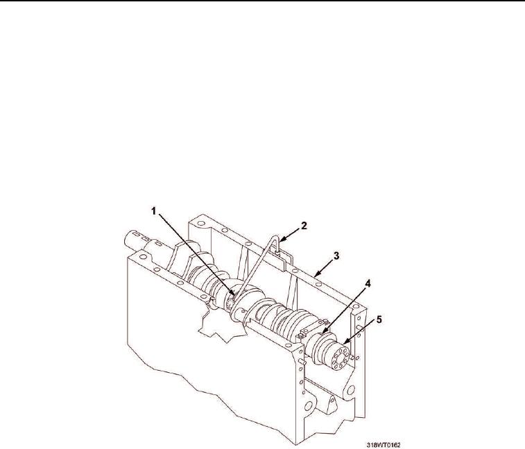
Measure the crankshaft (Figure 3, Item 5) bow.
a.
Support the crankshaft (Figure 3, Item 5) on the first (one) and last (fifth) main bearing journals
(Figure 3, Item 4) in an inverted engine block (Figure 3, Item 3) with all but the front and rear bearings
removed.
b.
Attach dial indicator to engine block (Figure 3, Item 3) at the third main bearing journal
(Figure 3, Item 4).
c.
Rotate crankshaft (Figure 3, Item 5) by hand. Observe dial indicator for run out indication. Run out limit
shall not exceed 0.004 in. If run out exceeds limits replace crankshaft.
d.
Repeat Steps b and c for journals two and four. Run out limit shall not exceed 0.002 in. If run out
exceeds limits replace crankshaft.
Figure 3. Checking Crankshaft Bow.
NOTE
Ensure that all crankshaft measurements are accurate within 0002 in. (0.00051 cm).
7.
Measure connecting rod bearing journals (Figure 4, Item 1) and main bearing journals (Figure 4, Item 1) in
several places on the circumference to determine taper out, out-of-round and bearing clearances.
a.
Connecting rod journal (Figure 4, Item 1) diameter should be 2.9985 to 3.0002 in. (7.616 to 7.621 cm).
Replace crankshaft if out of tolerance.
b.
Connecting rod journal (Figure 4, Item 1) width should be 2.652 to 2.648 in. (6.726 to 6.736 cm).
Replace crankshaft if out of tolerance.
c.
Main bearing journal (Figure 4, Item 2) diameter should be 4.4985 to 4.5002 in. (11.426 to 11.431 cm).
Replace crankshaft if out of tolerance.
d.
Main bearing journal (Figure 4, Item 2) width should be 1.495 to 1.505 in (3.797 to 3.823 cm). Replace
crankshaft if out of tolerance.

