
TM 55-2815-574-24
0159
REMOVAL - Continued
3.
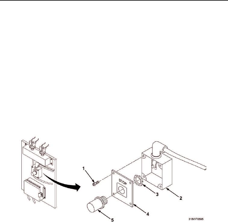
Remove four capscrews (Figure 2, Item 1) securing cover (Figure 2, Item 4) on box (Figure 2, Item 2).
4.
Remove cover (Figure 2, Item 4) from box (Figure 2, Item 2).
5.
Tag and disconnect wiring from pushbutton (Figure 2, Item 5).
6.
Remove large hex nut (Figure 2, Item 3) securing pushbutton (Figure 2, Item 5) to cover (Figure 2, Item 4).
7.
Remove pushbutton (Figure 2, Item 5) from cover (Figure 2, Item 4). Discard pushbutton.
END OF TASK
INSTALLATION
1.
Install new pushbutton (Figure 2, Item 5) on cover (Figure 2, Item 4).
2.
Install large hex nut (Figure 2, Item 3) to secure pushbutton (Figure 2, Item 5) to cover (Figure 2, Item 4).
Tighten large hex nut (Figure 2, Item 3).
3.
Connect wiring to pushbutton (Figure 2, Item 5) and remove tags.
4.
Position cover (Figure 2, Item 4) on box (Figure 2, Item 2).
5.
Install four capscrews (Figure 2, Item 1) to secure cover (Figure 2, Item 4) on box (Figure 2, Item 2). Tighten
capscrews (Figure 2, Item 1).
Figure 2. Stop Button Box.
6.
Remove LO/TO from A3 breaker switch. Refer to FM 4-01.502 for LO/TO procedure.
END OF TASK