
TM 55-2815-574-24
0074
INSPECT
NOTE
The piston crown, bearing and pin must be replaced as an assembly. The piston skirt may be
replaced separately.
1.
Inspect the piston crown (12) and piston skirt (11) for scoring, heat damage and excessive wear. Replace
damaged parts.
2.
Inspect the ring groove lands and steps for any evidence of overheating or cracking. Replace damaged parts.
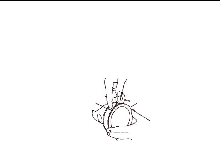
3. Check the tapered fire ring groove width in the piston crown (12) with groove gage.
FIRE GROOVE
12
RING
a. Slide the NO-GO wire 0.106 in. dia all the way around the fire ring groove. If the wire is below or flush at
any one area, the piston crown (12) must be replaced.
b.
Slide the GO wire 0.100 in. dia all the way around the fire ring groove. The GO wire should be flush or
protrude slightly.
4.
Check the head of the piston crown (12) for small cracks using the fluorescent magnetic particle method. Replace
piston crown (12) as necessary.
5.
Measure the piston crown (12) as follows.
a.
Measure the saddle to crown distance. It must be a minimum of 2.7025 in. (6.86435 cm) and a maximum of
2.7095 in. (6.88213 cm) Replace damaged parts.
b.
Measure the diameter at the top. It should measure a minimum of 4.8104 in. (12.21841 cm) and a maximum
of 4.8134 in. (12.22603 cm) Replace damaged parts.
c.
Measure the diameter below both compression rings. It should measure a minimum of 4.823 in.
(12.22603 cm) and a maximum of 4.8303 in. (12.26896 cm) Replace damaged parts.
d.
Measure the diameter above and below the seal ring groove. It should measure a minimum of 4.4650 in.
(11.3411 cm) and a maximum 4.4750 in. (11.3665 cm) Replace damaged parts.
e.
Measure the diameter above and below the bearing saddle. It should measure a minimum of 3.2360 in.
(8.21944 cm) and a maximum of 3.2370 in. (8.22198 cm) Replace damaged parts.
6. Measure the piston skirt (11) as follows.
0074-5