TM 55-2815-574-24
0074
HONE THE CYLINDER LINER Continued
{3} Clamp the liner into place with hold down clamp.
{4} Measure the distance from the top of the block to the top of the cylinder liner (15). The liner (15) must
be a minimum of 0.04187 in. (0.010634 cm) to a maximum of 0.0482 in. (0.12242 cm)
{5} Remove the clamp.
{6} Remove the liner (15).
f.
Calculate the variation in depth between adjacent liners. There cannot be more than 0.0015 in. (0.00381 cm)
between adjacent liners.
END OF TASK
ASSEMBLE
NOTE
On new bearings, there is a 0.0005 in. (0.00127 cm) to 0.0105 in. (0.02667 cm) clearance between
the edge of the bearing and the groove in the piston crown (9). The bearings should slide in
without force.
1.
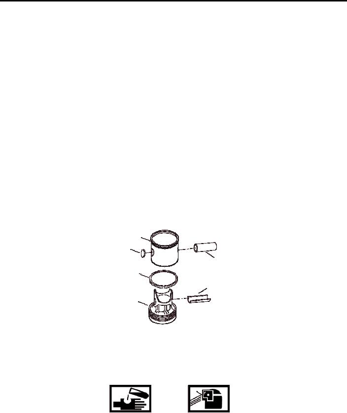
Install the piston pin bushing (14) into the piston crown (12).
11
7
10
13
14
12
2. Install the new ring (13) into the counterbore of skirt (11) and
3.
Verify the end gap is a minimum of 0.0020 in. (0.00508 cm) and a maximum of 0.0170 in. (0.04318 cm).
WARNING
Fuel/Oil may cause irritation to eyes or skin. Wear protective goggles, gloves, and clothing.
Failure to comply may result in personnel injury or death.
4. Coat the fluoroelastomer ring (13) with engine oil.
5.
Install fluoroelastomer ring (13) on the piston crown (12) and ensure that it spins freely.
6.
Measure the side clearance to be no less than 0.0005 in. (0.00127 cm) and no more than 0.0030 in. (0.00762 cm).
7.
Push the piston skirt (11) over the fluoroelastomer ring (13) on the piston crown (12).
0074-9

