TM 55-2815-574-24
0074
FIT AND MEASURE THE PISTON RINGS AND THE PISTON - Continued
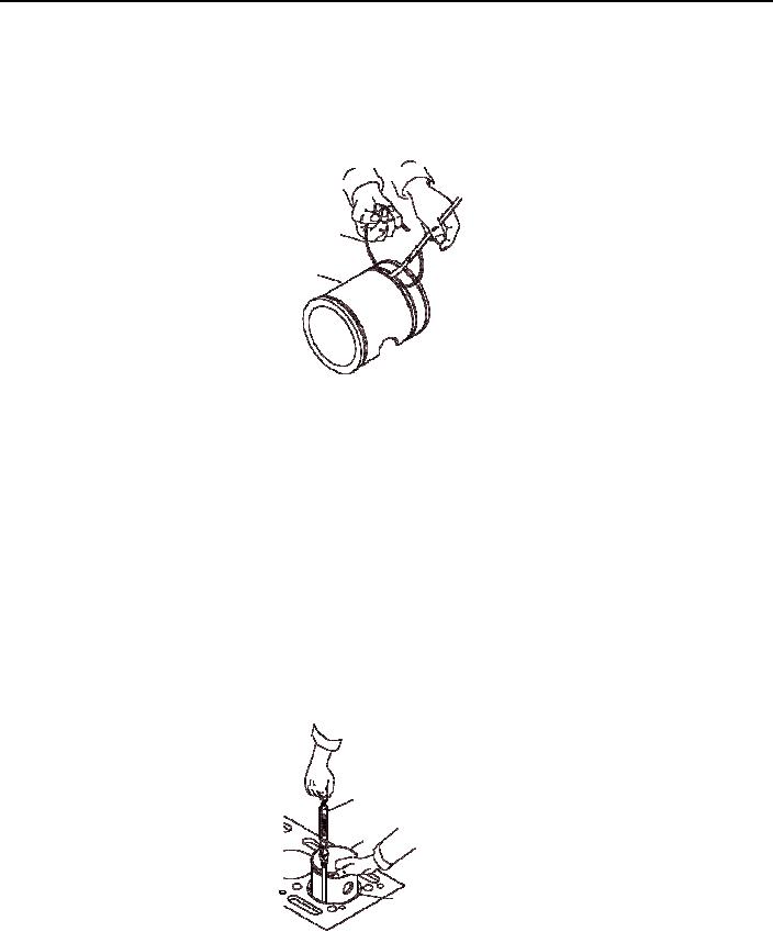
2. Measure the piston ring side clearance.
a.
Ensure the piston ring grooves are clean and free of debris.
b. Support the piston (1) on its side and place the outer edge of the piston rings (3 or 5) in the piston ring groove.
3
5
1
c.
Using a feeler gage between one of the rings (5) and the piston ring groove, measure the clearance as follows.
{1} Measure the top fire ring, it should have a side clearance not less than 0.0010 in. (0.00254 cm) and not
more than 0.0050 in. (0.0127 cm).
{2} Measure the middle compression ring, it should have a side clearance not less than 0.0100 in.
(0.0254 cm) and not more than 0.0130 in. (0.03302 cm).
{3} Measure the bottom compression ring, it should have a side clearance not less than 0.0040 in.
(0.01016 cm) and not more than 0.0070 in. (0.01778 cm).
d.
Follow the same procedure to measure clearance in 90 incriments around the piston (1).
FIT THE PISTON
1. Measure the piston skirt (11) lengthwise and crosswise of the piston pin journal.
2.
With the cylinder liner (2) installed in the block, hold cylinder (1) upside down in the liner (2).
FEELER GAUGE
1
2
3.
Measure the clearance in four places 90 apart.
a. Use spring scale feeler gage set to measure the clearance between the piston (1) and liner (2), a minimum of
0.0051 in. (0.01295 cm) or a maximum clearance of 0.0120 in. (0.03048 cm) is allowed.
b.
Use the spring scale to measure six lb of pull to remove the feeler gage.
END OF TASK
0074-12

