
TM 55-2815-574-24
0137
REMOVAL
1.
Place drain pan under filter cover (Figure 1, Item 6).
WARNING
Accidental or intentional introduction of liquid contaminants into the environment
may result in a violation of state, federal, and military regulations. Refer to local
environmental office for information concerning storage, use, and disposal of
these liquids. Failure to comply may cause damage to environment and health
of personnel. Seek medical attention in the event of injury.
Fuel/solvent/oil is slippery and may cause falls. Wipe up spillage immediately with
rags. Dispose of materials in accordance with local hazardous waste disposal
procedures. Failure to comply may result in personnel injury or death and/or
damage to equipment.
2.
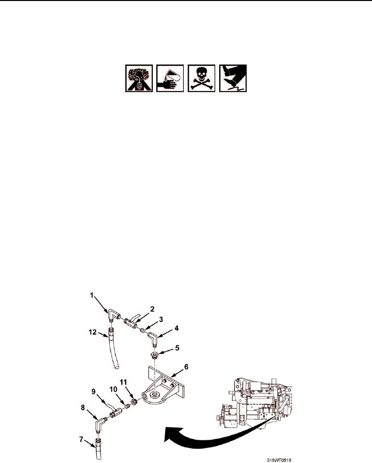
Remove hose (Figure 1, Item 7) from elbow (Figure 1, Item 8), allowing coolant to drain into drain pan.
3.
Remove elbow (Figure 1, Item 8), shutoff valve (Figure 1, Item 9), nipple (Figure 1, Item 10), and bushing
(Figure 1, Item 11) from filter cover (Figure 1, Item 6).
4.
Remove hose (Figure 1, Item 12) from elbow (Figure 1, Item 1), allowing coolant to drain into drain pan.
5.
Remove elbow (Figure 1, Item 1) from shutoff valve (Figure 1, Item 2).
6.
Remove shutoff valve (Figure 1, Item 2) from nipple (Figure 1, Item 3).
7.
Remove nipple (Figure 1, Item 3) and elbow (Figure 1, Item 4) from bushing (Figure 1, Item 5).
8.
Remove bushing (Figure 1, Item 5) from filter head (Figure 1, Item 6).
Figure 1. Filter Head Cover Hoses.