
TM 55-2815-574-24
0174
INTRODUCTION - Continued
2.
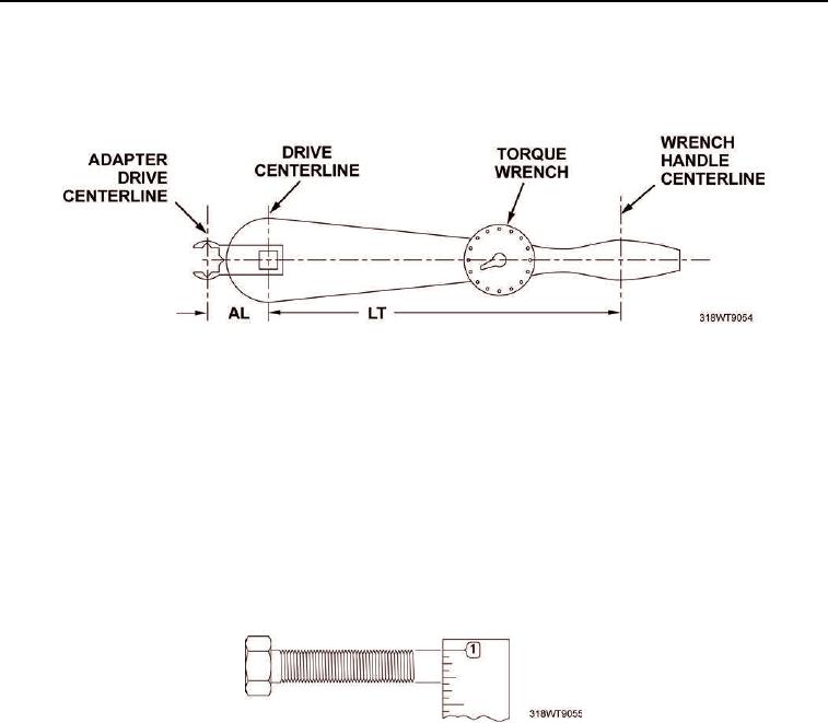
If the adapter used increases the distance between the center of the torque wrench handle and the center
of the drive, first find the desired torque for the fitting, then calculate as follows:
Figure 2. Torque Wrench Adapter Centerline.
a.
Multiply DT by LT.
b.
Add AL and LT.
c.
Divide the first answer by the second answer to find AT.
TORQUE TABLES
How To Use Torque Tables
1.
Measure the diameter of the bolt to be torqued.
Figure 3. Bolt Diameter.