
TM 55-2815-574-24
0173
INSTALLATION
1.
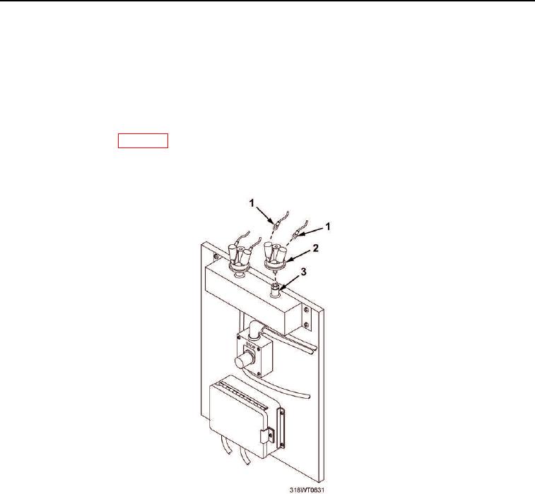
Wrap new fuel oil pressure switch (Figure 3, Item 2) threads with antiseizing tape.
2.
Install fuel oil pressure switch (Figure 3, Item 2) in mount fitting (Figure 3, Item 3) by turning clockwise.
Tighten fuel oil pressure switch (Figure 3, Item 2).
3.
Connect wiring (Figure 3, Item 1) to fuel oil pressure switch (Figure 3, Item 2) and remove tags.
4.
Remove LO/TO from A3 breaker switch. Refer to FM 4-01.502 for LO/TO procedure.
5.
Prime fuel system (WP 0078).
6.
Start engine (TM 55-1925-205-10).
7.
Check fuel oil pressure switch (Figure 3, Item 2) for leaks.
Figure 3. Fuel Oil Pressure Switch.
END OF TASK