3.
filling
fuel.
4.
Avoid fueling equipment with the wrong fuel or
hydraulic systems or cooling systems with the
Maintain accurate records in a log documenting
amounts of fuel issued, by equipment USN number.
5. Ensure fuel availability for contingency
.
readiness, daily transportation, and construction
operations.
6. Maintain fire extinguishers on the tanker truck
as set forth in the U.S. Army Corps of Engineers, Safety
and Health Requirements Manual, EM 385-1-1.
7. Be alert to avoid environmental pollution. Fuel
spillage can be disastrous.
8. Daily communicate with the yard boss,
dispatcher, and the transportation supervisor.
9. Be a qualified professional operator of the fuel
truck.
Fuel-Handling Vehicle
Fuel-handling vehicles are classified as fuel tank
trucks or fuel tank semitrailers. Each vehicle has
distinguishing characteristics (model, size, and
capacity). The purpose of fuel-handling vehicles is to
load, haul, and discharge fuel to other vehicles, aircraft,
or fuel depots.
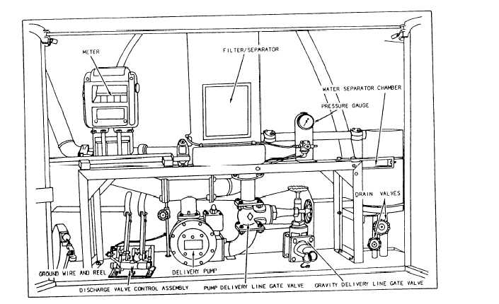
DESCRIPTION.— A typical fuel tank truck is
equipped with a tank body divided into compartments.
Each compartment has a manhole and filler cover
assembly, bottom sump or well, and discharge valves
with screen assemblies and drainpipes. The drainpipes
end in a manifold in the equipment Compartment. The
compartment (fig. 6-19) also houses a delivery pump, a
discharge valve control assembly, a pump delivery line
gate valve, an automatic dump valve, drain tube valves,
a gravity line gate valve, a filter separator, a pressure
gate, a meter, a water separator chamber, and a
grounding cable.
The delivery pump is powered by the power takeoff
(PTO), which is controlled by the PTO lever located in
the cab of the truck. The lever is moved backward to
the ENGAGED position to engage the PTO which
causes the pump to operate. The lever is moved forward
to the DISENGAGED position to disengage the PTO
and to stop the pump.
The discharge valve control assembly levers control
the discharge valves located at the bottom of each tank
Figure 6-19.-Dispensing equipment compartment.
6-25