Construction stakes, sometimes referred to as
grade stakes, are the guides and reference markers for
earthwork operations to show cuts, fills, drainage,
alignment, and boundaries of the construction area.
The number of stakes and the information contained on
them will vary with the project as to whether they are
temporary or permanent. Stakes are usually placed by a
three- to five-person survey party using a level, a level
rod, a tape, and range poles.
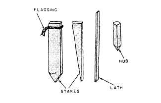
A “stake” is defined as any wooden lath, stake,
or hub. “Hub stakes” are 2 inches by 2 inches by
approximately 12 inches and are used primarily for
well-defined surveyors’ reference points, with the red
and blue tops used in finished grade work. Stakes will
vary in shape and size according to their use and the
materials available for their manufacture. Several
stakes are shown in figure 15-22. Stakes range in size
from the ordinary rough plaster lath to 1- by 2- by
3-inch cross-sectional lumber with lengths varying
from 18 inches to 48 inches.
All reference hubs, markers, and bench marks
established by the Engineering Aids (EAs) for project
control or alignment are protected by guard stakes.
Guard stakes are used as a means of locating the points
needed. Some color of bunting or flagging (a narrow
strip of cloth or plastic) may be tied around the top of
the stake. Station identification is placed on the front of
the stake and any other pertinent data on the back.
In some situations, the survey crew will establish
grades only on the centerline stakes, while edge-of-road
and slope stakes are set by the project supervisor and
helpers. Alignment, shoulder, and slope stakes should
be 1 inch by 2 inches in cross section, smooth on four
sides, and about 2 feet in length. Actual grade desired
is indicated by a reference mark, called a crowfoot, and
numbers to show the amount of cut or fill.
These stakes should be marked with the following
information:
. The stationing or location of any part of the road,
runway, or taxiway relative to a starting point or refer-
ence
. The amount of cut and fill from the existing
ground surface or reference mark on the stake
. The distance from the center line to the stake
location and from the center line to the ditch line
In most earthwork, measurements are made and
written by the decimal system as used in construction
engineering. Most markings on construction stakes
will be in feet and tenths of a foot. A stake marked C35
means that a cut must be made 3.5 feet. To convert .5
foot to inches, multiply the decimal fraction by 12.
For example: .5 x 12 inches = 6 inches; .25 x 12
inches = 3 inches.
STARTING POINT
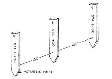
The “starting point” of a survey is also called the
starting station and is numbered 0 + 00. The next
station is 100 feet farther away and is numbered 1 + 00.
The next station, which is 200 feet beyond the starting
point, is then numbered 2 + 00, and so forth. All stations
that end with 00 are called full stations. As shown in
figure 15-23, stations may be abbreviated STA on the
stakes.
On sharp curves or on rough ground, the stakes may
be closer together than on the straightaway. Stations,
located at a distance shorter than 100 feet from the
preceding station, are known as plus stations, such as
Figure 15-22.—Types of stakes.
Figure 15-23.—Starting point.
15-16


