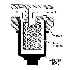
STRAINERSStrainers are used primarily to catch only verylarge particles and will be found in applicationswhere this type of protection is required. Mosthydraulic systems have a strainer in the reservoirat the inlet to the suction line of the pump. Astrainer is used in lieu of a filter to reduce itschance of being clogged and starving the pump.However, since this strainer is located in thereservoir, its maintenance is frequently neglected.When heavy dirt and sludge accumulate on thesuction strainer, the pump soon begins to cavitate.Pump failure follows quickly.FILTERSThe most common device installed inhydraulic systems to prevent foreign particles andcontamination from remaining in the system arereferred to as filters. They may be located in thereservoir, in the return line, in the pressure line,or in any other location in the system where thedesigner of the system decides they are needed tosafeguard the system against impurities.Filters are classified as full flow andproportional or partial flow. In the full-flow typeof filter, all the fluid that enters the unit passesthrough the filtering element, while in theproportional-flow type, only a portion of the fluidpasses through the element.Full-Flow FilterThe full-flow filter provides a positive filteringaction; however, it offers resistance to flow,particularly when the element becomes dirty.Hydraulic fluid enters the filter through the inletport in the body and flows around the filterelement inside the filter bowl. Filtering takes placeas the fluid passes through the filtering elementand into the hollow core, leaving the dirt andimpurities on the outside of the filter element.The filtered fluid then flows from the hollowcore through the outlet port and into the system(fig. 9-10).Some full-flow filters are equipped with acontamination indicator (fig. 9-11). Theseindicators, also known as differential pressureindicators, are available in three types—gaugeindicators, mechanical pop-up indicators, andelectrical with mechanical pop-up indicators. Ascontaminating particles collect on the filterelement, the differential pressure across theelement increases. In some installations usingFigure 9-10.—Full-flow hydraulic filter.gauges as indicators, the differential pressure mustbe obtained by subtracting the readings of twogauges located somewhere along the filter inletand outlet piping. For pop-up indicators, whenthe increase in pressure reaches a specific value,an indicator (usually in the filter head) pops out,signifying that the filter must be cleaned orreplaced. A low-temperature lockout feature isinstalled in most pop-up types of contaminationindicators to eliminate the possibility of falseindications due to cold weather because thepressure differential may be much higher with acold fluid due to increased viscosity.Filter elements used in filters that have acontamination indicator are not normallyremoved or replaced until the indicator isactuated. This decreases the possibility of systemcontamination from outside sources due tounnecessary handling.The use of the nonbypassing type of filtereliminates the possibility of contaminated fluidbypassing the filter element and contaminating theentire system. This type of filter will minimize thenecessity for flushing the entire system and lessenthe possibility of failure of pumps and othercomponents in the system.A bypass relief valve is installed in some filters.The bypass relief valve allows the fluid to bypassthe filter element and pass directly through theoutlet port in the event that the filter elementbecomes clogged. These filters may or may notbe equipped with the contamination indicator.Figure 9-11 shows a full-flow bypass-type9-8
Integrated Publishing, Inc. - A (SDVOSB) Service Disabled Veteran Owned Small Business