installations. A typical reservoir for use with
ground and ship installations is shown in figure
9-1. This type of reservoir is made of hot rolled
steel plates and has welded seams. The ends extend
below the bottom of the reservoir and serve as
supports. The bottom of the reservoir is convex,
and a drain plug is incorporated at the lowest
point.
Nonpressurized reservoirs are also used in
several transport-,
patrol-, and utility-type
aircraft. These aircraft are not designed for violent
maneuvers and, in some cases, do not fly at high
altitude. Those aircraft that have nonpressurized
reservoirs installed and that fly at high altitudes
have the reservoirs installed within a pressurized
area. (High altitude in this situation means an
altitude where atmospheric pressure is inadequate
to maintain sufficient flow of fluid to the
hydraulic pumps.)
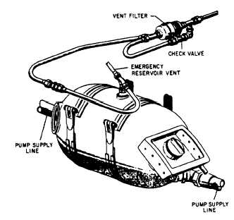
Most nonpressurized aircraft reservoirs are
constructed in a cylindrical shape (fig. 9-2). The
outer housing is manufactured from a strong
corrosion-resistant metal. Filter elements are
normally installed internally within the reservoir
to clean returning system hydraulic fluid. Some
of the older aircraft have a filter bypass valve
installed to allow fluid to bypass the filter if the
filter becomes clogged. Reservoirs that are filled
by pouring fluid directly into them have a filler
(finger) strainer assembly installed in the filler well
to strain out impurities as the fluid enters the
reservoir.
Figure 9-2.—Nonpressurized aircraft reservoir.
The quantity of fluid in the reservoir is
indicated by either a glass tube, a directing gauge,
or a float-type rod, which is visible through a
transparent dome installed on the reservoir.
PRESSURIZED RESERVOIRS
A pressurized reservoir is required in hydraulic
systems where atmospheric pressure is insufficient
to maintain a net positive suction head (NPSH)
to the pump. There are two common types of
pressurized reservoirs—fluid-pressurized and
air-pressurized.
Fluid-Pressurized Reservoir
Some aircraft hydraulic systems use fluid
pressure for pressurizing the reservoir. The
reservoir shown in figure 9-3 is of this type. This
reservoir is divided into two chambers by a
floating piston. The piston is forced downward
in the reservoir by a compression spring within
the pressurizing cylinder and by system pressure
entering the pressurizing port of the cylinder.
The pressurizing port is connected directly to
the pressure line. When the system is pressurized,
pressure enters the pressure port, thus pressurizing
the reservoir. This pressurizes the pump suction
line and the reservoir return line to the same
pressure.
The reservoir shown in figure 9-3 has five
ports—pump suction, return, pressurizing,
overboard drain, and bleed. Fluid is supplied to
the pump through the pump suction port. Fluid
returns to the reservoir from the system through
the return port. Pressure from the pump enters
the pressurizing cylinder in the top of the reservoir
through the pressurizing port. The overboard
drain port is used to drain the reservoir while
performing maintenance, and the bleed port is
used as an aid when servicing the reservoir.
Air-Pressurized Reservoirs
Air-pressurized reservoirs, such as the one
shown in figure 9-4, are currently used in many
high-performance naval aircraft. The reservoir is
cylindrical in shape and has a piston installed
internally to separate the air and fluid chambers.
Air pressure is usually provided by engine bleed
air. The piston rod end protrudes through the
reservoir end cap and indicates the fluid quantity.
The quantity indication may be seen by inspecting
the distance the piston rod protrudes from the
reservoir end cap. The reservoir is provided with
9-2