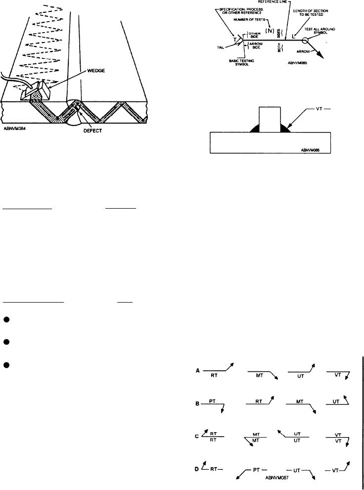
Figure 11-14.--Standard location of elements on a
nondestructive testing symbol.
Figure 11-13.--Scanning a weld.
Figure 11-15.--Arrow connecting the reference line and part
being tested.
performed. The four basic nondestructive testing
symbols are as follows:
indicated by the test symbol on the side of the reference
line away from the reader, as shown in view B. Tests to
SYMBOL
TYPE OF TEST
be made on both sides of the part are indicated by test
RT
Radiographic
symbols on both sides of the reference line, as shown in
MT
Magnetic Particle
view C. When nondestructive testing symbols have no
arrow-side or other-side significance, the testing
PT
Liquid Penetrant
symbols are centered on the reference line, as shown in
UT
Ultrasonic
view D.
An assembled nondestructive testing symbol
When a specification, process, classification, or
consists of the following elements:
other reference is used with testing symbols, the
TAIL
REFERENCE LINE
reference is placed in the tail, as shown in figure 11-17.
Specification, process, classification, or other reference
Arrow
Extent of test
need not be used on testing symbols when the testing
procedure is prescribed elsewhere.
Basic testing symbol
Specification, process,
(N) Number of tests
or other reference
Each of these elements should be used as necessary.
They will have standard locations with respect to each
other, as shown in figure 11-14.
The arrow connects the reference line to the part to
be tested (fig. 11-15). The side of the part to which the
arrow points is called the arrow side of the part. The
side opposite the arrow is called the other side.
The location of testing symbols is shown in figure
11-16. Tests to be made on the arrow side of the part
are indicated by a test symbol on the side of the
reference line toward the reader, as shown in view A.
Tests to be made on the other side of the part are
Figure 11-16.--Location of testing symbols.
11-15


