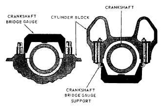
Figure 3-35.—Crankshaft bridge gauge.
leave an impression in the soft bearing metal because
the gauge material is softer than the bearing. To use this
method, place a length of the Plastigage of proper gauge
across the bearing. Then, assemble the bearing cap and
tighten it in place. DO NOT TURN the crankshaft, as
that will destroy the Plastigage. After you install and
properly fasten the bearing cap, remove it. Compare the
width of the crushed Plastigage with the Plastigage chart
to determine the exact clearance.
You must take measurements at specified intervals,
usually at every overhaul, to establish the amount of
bearing wear. Also take a sufficient number of
crankshaft journal diameter measurements at suitable
points to determine possible out-of-roundness.
With some types of engines, a crankshaft bridge
gauge (fig. 3-35) is used to check the wear of the main
bearing shells. To use the gauge, place it on the
crankshaft and measure the clearance between the
bridge gauge and the shaft with a feeler gauge. Any
variation between the measured clearance and the
correct clearance (usually stamped on the housing of
each bearing) indicates that main bearing wear has
occurred. The maximum limits of wear are listed in the
manufacturer’s technical manual. Some engine
manufacturers recommend that bridge gauge readings
be taken at every overhaul in conjunction with crank
web deflection measurements.
The important point to remember is that if you
cannot overhaul an engine due to lack of space,
manpower, or expertise, you may request outside help
by using an OPNAV Form 4790/2K. This form, when
used as a work request, will be sent to a ship intermediate
maintenance activity (SIMA). The SIMA will then
accept or reject the work request. If the work request is
accepted, the SIMA will order all repair parts, overhaul
the engine, and perform an operational test according to
the manufacturers’ technical manuals and the NSTM,
chapter 233.
As stated earlier in this section, maintenance cards,
manufacturers’ maintenance manuals, and various other
instructions discuss repair procedures in detail.
Therefore, this chapter will be limited to general
information on some of the troubles encountered during
overhaul, the causes of such troubles, and the methods
of repair.
TROUBLESHOOTING
INTERNAL-COMBUSTION ENGINES
The
procedures
for
troubleshooting
internal-combustion engines are somewhat similar for
both diesel and gasoline engines. In many instances, the
information that follows will apply to both types of
engine. However, it also discusses principal differences.
Since most of the internal-combustion engines used by
the Navy are diesel, the following sections deal
primarily with this type of engine.
This chapter is concerned with troubles that occur
both when an engine is starting and running. The
troubles are chiefly the kind that can be identified by
erratic engine operation, warnings by instruments, or
inspection of the engine parts and systems and that can
be corrected without major repair or overhaul. There is
also a section devoted to the systems of the gasoline
engine that are basically different from those of the
diesel engine.
Keep in mind that the troubles listed here are general
and may or may not apply to a particular diesel engine.
When you work with a specific engine, check the
manufacturer’s technical manual and any instructions
issued by the Naval Sea Systems Command.
An engine may continue to operate even when a
serious casualty is imminent. However, symptoms are
usually present. Your success as a troubleshooter
depends partially upon your ability to recognize these
symptoms when they occur. You will use most of your
senses to detect trouble symptoms. You may see, hear,
smell, or feel the warning of trouble to come. Of course,
common sense is also a requisite. Another factor in your
success as a troubleshooter is your ability to locate the
trouble once you decide something is wrong with the
equipment. Then, you must be able to determine as
rapidly as possible what corrective action to take. In
3-22


