seated (shut). The action of the poppet is similar
to that of the valves in an automobile engine. In
most valves the poppet is held in the seated
position by a spring.
The valve consists primarily of a movable
poppet which closes against the valve seat. In the
closed position, fluid pressure on the inlet side
tends to hold the valve tightly closed. A small
amount of movement from a force applied to the
top of the poppet stem opens the poppet and
allows fluid to flow through the valve.
The use of the poppet as a-valving element is
not limited to directional control valves.
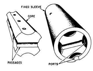
Rotary Spool
The rotary spool directional control valve
(fig. 6-22) has a round core with one or more
passages or recesses in it. The core is mounted
within a stationary sleeve. As the core is rotated
within the stationary sleeve, the passages or
recesses connect or block the ports in the sleeve.
The ports in the sleeve are connected to the
appropriate lines of the fluid system.
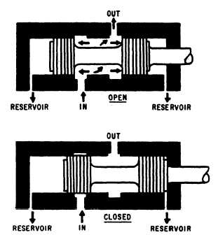
Sliding spool
The operation of a simple sliding spool
directional control valve is shown in figure 6-23.
The valve is so-named because of the shape of the
valving element that slides back and forth to block
and uncover ports in the housing. (The sliding
element is also referred to as a piston.) The inner
piston areas (lands) are equal. Thus fluid under
pressure which enters the valve from the inlet ports
CHECK VALVE
Figure 6-22.—Parts of a rotary spool directional control
valve.
Figure 6-23.—Two-way, sliding spool directional control
valve.
acts equally on both inner piston areas regardless
of the position of the spool. Sealing is usually
accomplished by a very closely machined fit
between the spool and the valve body or sleeve.
For valves with more ports, the spool is designed
with more pistons or lands on a common shaft.
The sliding spool is the most commonly used type
of valving element used in directional control
valves.
Check valves are used in fluid systems to
permit flow in one direction and to prevent flow
in the other direction. They are classified as
one-way directional control valves.
The check valve may be installed inde-
pendently in a line to allow flow in one direction
only, or it may be used as an integral part of
globe, sequence, counterbalance, and pressure-
reducing valves.
Check valves are available in various designs.
They are opened by the force of fluid in motion
flowing in one direction, and are closed by fluid
attempting to flow in the opposite direction. The
force of gravity or the action of a spring aids in
closing the valve.
6-16