When the primary actuating unit completes its
operation, pressure in the line to the actuating unit
increases sufficiently to overcome the force of the
spring, and the piston rises. The valve is then in
the open position (fig. 6-16, view B). The fluid
entering the valve takes the path of least resistance
and flows to the secondary unit.
A drain passage is provided to allow any fluid
leaking past the piston to flow from the top of
the valve. In hydraulic systems, this drain line is
usually connected to the main return line.
Mechanically Operated Sequence Valve
The mechanically operated sequence valve
(fig. 6-17) is operated by a plunger that extends
through the body of the valve. The valve is
mounted so that the plunger will be operated by
the primary unit.
A check valve, either a ball or a poppet, is
installed between the fluid ports in the body. It
can be unseated by either the plunger or fluid
pressure.
Port A (fig. 6-17) and the actuator of the
primary unit are connected by a common line.
Port B is connected by a line to the actuator of
the secondary unit. When fluid under pressure
flows to the primary unit, it also flows into the
sequence valve through port A to the seated check
valve in the sequence valve. In order to operate
the secondary unit, the fluid must flow through
the sequence valve. The valve is located so that
the primary unit depresses the plunger as it
completes its operation. The plunger unseats
the check valve and allows the fluid to flow
Figure 6-17.—Mechanically operated sequence valve.
through the valve, out port B, and to the
secondary unit.
This type of sequence valve permits flow in
the opposite direction. Fluid enters port B and
flows to the check valve. Although this is return
flow from the actuating unit, the fluid overcomes
spring tension, unseats the check valve, and flows
out through port A.
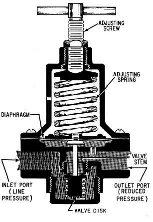
PRESSURE-REDUCING VALVES
Pressure-reducing valves provide a steady
pressure into a system that operates at a lower
pressure than the supply system. A reducing valve
can normally be set for any desired downstream
pressure within the design limits of the valve. Once
the valve is set, the reduced pressure will be
maintained regardless of changes in supply
pressure (as long as the supply pressure is at least
as high as the reduced pressure desired) and
regardless of the system load, providing the load
does not exceed the design capacity of the reducer.
Figure 6-18.—Spring-loaded pressure-reducing valve.
6-12