when the valve is open. A small piston (9) is
attached to the bottom of the spool valve.
When the valve is in the closed position, the
top piston of the spool valve blocks the discharge
port (8). With the valve in this position, fluid
flowing from the actuating unit enters the inlet
port (5). The fluid cannot flow through the valve
because discharge port 8 is blocked. However,
fluid will flow through the pilot passage (6) to the
small pilot piston. As the pressure increases, it acts
on the pilot piston until it overcomes the preset
pressure of spring 3. This forces the valve spool
(4) up and allows the fluid to flow around the
shaft of the valve spool and out discharge port
8. Figure 6-20 shows the valve in this position.
During reverse flow, the fluid enters port 8. The
spring (3) forces valve spool 4 to the closed
position. The fluid pressure overcomes the spring
tension of the check valve (7). The check valve
opens and allows free flow around the shaft of
the valve spool and out through port 5.
The operating pressure of the valve can be
adjusted by turning the adjustment screw (1),
which increases or decreases the tension of the
spring. This adjustment depends on the weight
that the valve must support.
It is normal for a small amount of fluid to leak
around the top piston of the spool valve and into
the area around the spring. An accumulation
would cause additional pressure on top of the
spool valve. This would require additional
pressure to open the valve. The drain (2) provides
a passage for this fluid to flow to port 8.
DIRECTIONAL CONTROL VALVES
Directional control valves are designed to
direct the flow of fluid, at the desired time, to the
point in a fluid power system where it will do
work. The driving of a ram back and forth in its
cylinder is an example of when a directional
control valve is used. Various other terms are used
to identify directional valves, such as selector
valve, transfer valve, and control valve. This
manual will use the term directional control valve
to identify these valves.
Directional control valves for hydraulic
and pneumatic systems are similar in design
and operation. However, there is one major
difference. The return port of a hydraulic valve
is ported through a return line to the reservoir,
while the similar port of a pneumatic valve,
commonly referred to as the exhaust port, is
usually vented to the atmosphere. Any other
differences are pointed out in the discussion of
the valves.
Directional control valves may be operated by
differences in pressure acting on opposite sides
of the valving element, or they maybe positioned
manually, mechanically, or electrically. Often two
or more methods of operating the same valve will
be used in different phases of its action.
CLASSIFICATION
Directional control valves may be classified in
several ways. Some of the different ways are by
the type of control, the number of ports in the
valve housing, and the specific function of the
valve. The most common method is by the type
of valving element used in the construction of the
valve. The most common types of valving
elements are the ball, cone or sleeve, poppet,
rotary spool, and sliding spool. The basic
operating principles of the poppet, rotary spool,
and sliding spool valving elements are discussed
in this text.
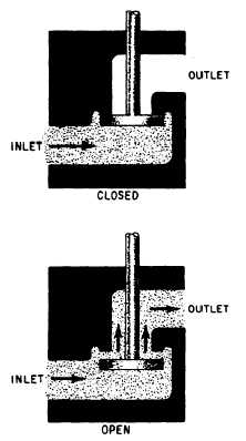
Poppet
The poppet fits into the center bore of the seat
(fig. 6-21). The seating surfaces of the poppet and
the seat are lapped or closely machined so that
the center bore will be sealed when the poppet is
Figure 6-21.—Operation of a simple poppet valve.
6-15