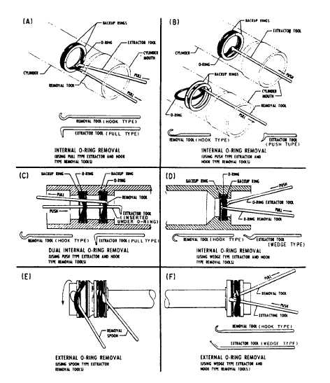
figure 7-9. These tools should be fabricated from
soft metal such as brass or aluminum; however,
tools made from phenolic rod, wood, or plastic
may also be used.
Tool surfaces must be well rounded, polished,
and free of burrs. Check the tools often, especially
the surfaces that come in contact with O-ring
grooves and critical polished surfaces.
Notice in figure 7-9, view A, how the
hook-type removal tool is positioned under the
O-ring and then lifted to allow the extractor tool,
as well as the removal tool, to pull the O-ring from
its cavity. View B shows the use of another type
of extractor tool in the removal of internally
installed O-rings.
In view C, notice the extractor tool positioned
under both O-rings at the same time. This method
of manipulating the tool positions both O-rings,
which allows the hook-type removal tool to
extract both O-rings with minimum effort. View
D shows practically the same removal as view C,
except for the use of a different type of extractor
tool.
The removal of external O-rings is less difficult
than the removal of internally installed O-rings.
Views E and F show the use of a spoon-type
extractor, which is positioned under the seal. After
the O-ring is dislodged from its cavity, the
spoon is held stationary while the piston is
simultaneously rotated and withdrawn. View F
is similar to view E, except that only one O-ring
is installed, and a different type of extractor tool
is used. The wedge-type extractor tool is inserted
beneath the O-ring; the hook-type removal tool
hooks the O-ring. A slight pull on the latter tool
removes the O-ring from its cavity.
After removing all O-rings, cleaning of the
affected parts that will receive new O-rings is
Figure 7-9.—O-ring tools and O-ring removal.
7-10


