mandatory. Ensure that the area used for such
installations is clean and free from all
contamination.
Remove each O-ring that is to be installed
from its sealed package and inspect it for defects
such as blemishes, abrasions, cuts, or punctures.
Although an O-ring may appear perfect at first
glance, slight surface flaws may exist. These are
often capable of preventing satisfactory O-ring
performance. O-rings should be rejected for flaws
that will affect their performance.
By rolling the ring on an inspection cone or
dowel, the inner diameter surface can be checked
for small cracks, particles of foreign material, and
other irregularities that will cause leakage or
shorten its life. The slight stretching of the ring
when it is rolled inside out will help to reveal some
defects not otherwise visible. A further check of
each O-ring should be made by stretching it
between the fingers, but care must be taken not to
exceed the elastic limits of the rubber. Following
these inspection practices will prove to be a
maintenance economy. It is far more desirable to
take care identifying and inspecting O-rings than to
repeatedly overhaul components with faulty seals.
After inspection and prior to installation,
lubricate the O-ring, and all the surfaces that it
must slide over with a light coat of the system fluid
or a lubricant approved for use in the system.
Consult the applicable technical instruction or
Naval Ships’ Technical Manual for the correct
lubricant for pneumatic systems.
Assembly must be made with care so that the
O-ring is properly placed in the groove and not
damaged as the gland is closed. During some
installations, such as on a piston, it will be
necessary to stretch the O-ring. Stretch the O-ring
as little and as uniformly as possible. Avoid rolling
or twisting the O-ring when maneuvering it into
place. Keep the position of the O-ring mold line
constant. O-rings should not be left in a twisted
condition after installation.
If the O-ring installation requires spanning or
inserting through sharp-threaded areas, ridges,
slots, and edges, use protective measures, such as
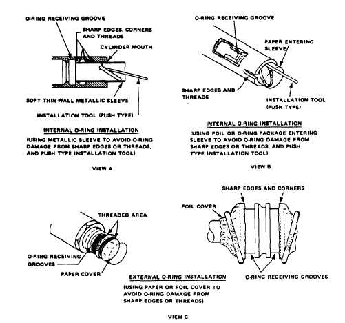
the O-ring entering sleeve (fig. 7-10, view A). If
Figure 7-10.–O-ring installation.
7-11


