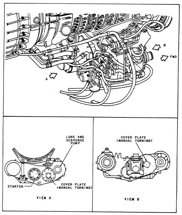
Figure 2-8.—Engine turning locations for borescope inspections.
Detailed procedures are provided for indexing and
reference point for distress reporting for each stage. You
rotating the engine on the MRC. Figures 2-9 and 2-10
should not concentrate on counting the blades. Instead,
show the accessory drive gear ratios and the locking lugs
concentrate on the specific condition of each airfoil as
used for indexing the compressor rotor. Zero reference
it passes. The forward and aft drive pads have different
for the compressor and HP turbine stages is established
drive ratios to the main rotor shaft. You may find it
by use of the locking lug blades. Establishing the zero
advantageous to use a torque multiplier to slow down
reference ensures a complete inspection for each stage.
and maintain better control over the main rotor speed.
It also provides you an immediate circumferential
Depending on the manual drive setup, you will be able
2-8