
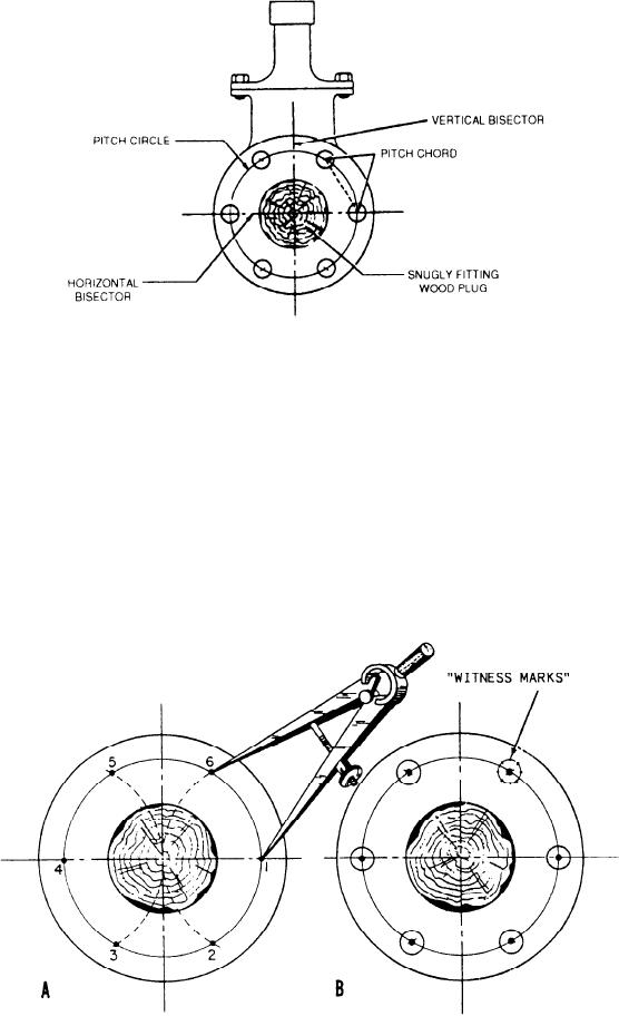
Figure 2-30.--Flange layout terminology.
circle with the dividers. Each pitch chord must be
circle and the horizontal bisector on the left-hand side
equal to the setting of the dividers. If it is not, you
of the flange point 4. Draw a small arc across the
have an error in hole mark placement that you must
pitch circle line at points 3 and 5. These points (1 to
6) are the centers for the holes. Check the accuracy of
correct before you center punch the marks for the
holes. After you are sure the layout is accurate, center
the pitch chords. To do this, leave the dividers set
punch the hole marks and draw a circle of appropriate
exactly as you had them set to draw the arcs. Starting
size around each center-punched mark and
from the located center of any hole, step around the
Figure 2-31.--Development of a 6-hole flange.
2-15