
Then, place the squaring head of a combination
square, as shown in view B. Secure the scale so the
end is in contact with the surface of the plate. Move
the surface gauge into position.
USING THE SINE BAR
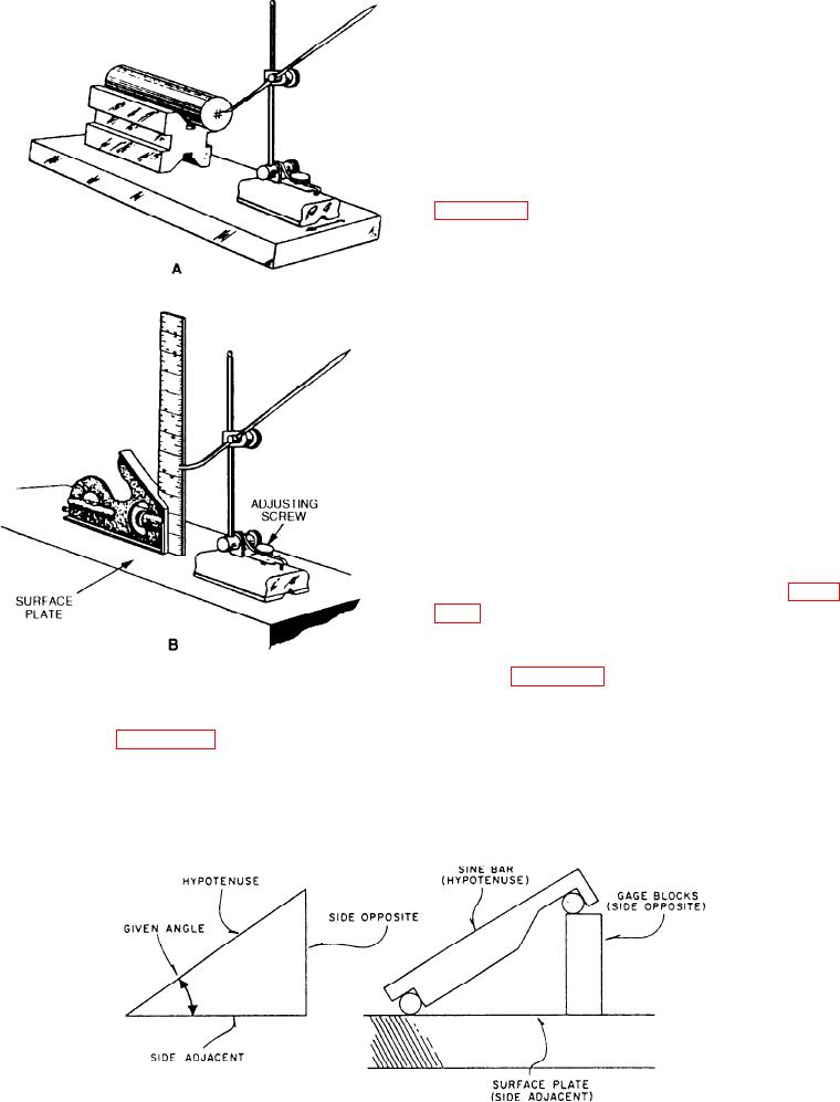
A sine bar is a precisely machined tool steel bar
used with two steel cylinders. In the type shown in
figure 2-25, the cylinders establish a precise distance
of either 5 inches or 10 inches from the center of one
to the center of the other, depending upon the model
used. The bar itself has accurately machined parallel
sides, and the axes of the two cylinders are parallel to
the adjacent sides of the bar within a close tolerance.
Equally close tolerances control the cylinder
roundness and freedom from taper. The slots or holes
in the bar are for convenience in clamping workpieces
to the bar. Although the illustrated bars are typical,
there is a wide variety of specialized shapes, widths,
and thicknesses.
The sine bar itself is very easy to set up and use.
You do need a basic knowledge of trigonometry to
understand how it works. When a sine bar is set up, it
always forms a right triangle. A right triangle has one
90-degree angle. The base of the triangle, formed by
the sine bar, is the surface plate, as shown in figure
2-25. The side opposite is made up of the gauge
blocks that raise one end of the sine bar. The
hypotenuse is always formed by the sine bar, as
shown in figure 2-25. The height of the gauge block
Figure 2-24.--Setting and using a surface gauge.
setting may be found in two ways. The first method is
to multiply the sine of the angle needed by the length
View A of figure 2-24 shows a surface gauge
of the sine bar. The sine of the angle may be found in
any table of natural trigonometric functions. For
V-block combination used to lay out a piece of stock.
example, if you had to set a 10-inch sine bar to check
To set a surface gauge for height, first clean the top of
a 305 angle on a part, you would first go to a table of
the surface plate and the bottom of the surface gauge.
Figure 2-25.--Setup of the sine bar.
2-12