
Figure 2-11.--Checking surface finish on the machine.
check the workpiece manually while it is in the
machine (fig. 2-11).
SURFACE ANALYZER
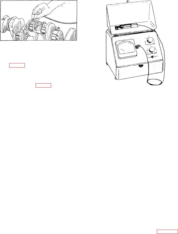
The surface analyzer (fig. 2-12) is a practical shop
instrument designed for the accurate measurement of
Figure 2-12.--Surface analyzer.
surface finish roughness. Like the profilometer, it
measures the irregularities of the surface finish and
relationship of the surfaces. That understanding will
records them in microinches. This is done by a tracer
help you plan the sequence of machining operations.
stylus, which registers the rise and fall of the peaks
and valleys on the finished surfaces. These variations
Mechanical drawing and layout are closely
are amplified and indicated on the electrical meter,
related subjects; knowledge of one will help you
calibrated to read in microinches.
understand the other. You also must know general
mathematics, trigonometry, and geometry, and how to
select and use tools for jobs related to layout and
LAYOUT METHODS
mechanical drawing. Study Mathematics, Volume I,
Layout is the term used to describe the marking of
NAVEDTRA 10069-D1; Mathematics, Volume 2-A,
metal surfaces to provide an outline for machining. A
NAVEDTRA 10062; Use and Care of Hand Tools and
layout is comparable to a single view (end, top, or
Measuring Tools, NAVEDTRA 12085, and Blueprint
side) of a part that is sketched directly on the
Reading and Sketching, NAVEDTRA 10077-F7, for
workpiece. The degree of difficulty depends on the
additional information.
intricacies of the part to be laid out and the number of
The following information applies to practically
operations required to make the part. A flange layout,
all layouts. Layout lines are formed by using a
for example, is relatively simple as the entire layout
reference edge or point on the stock or by using the
can be made on one surface of the blank flange.
surface plate as a base. Study carefully the section on
However, an intricate casting may require layout lines
geometric construction. It will help you make layouts
on more than one surface. This requires careful study
when you can't use a reference edge of the stock or a
and concentration to make sure the layout will have
surface plate mounting of the stock.
the same relationships as those shown on the drawing
(or sample) that you are using.
LINES SQUARE OR PARALLEL TO
When a part must be laid out on two or more
EDGES
surfaces, you may need to lay out one surface and
machine it to size before using further layout lines.
When scribing layout lines on sheet metal, hold
This prevents removal of layout lines on one surface
the scratch awl, or scribe, as shown in figure 2-13.
while you are machining another.
Lean it toward the direction in which it will be moved
and away from the straightedge. This will help you
The process of computing and transferring
scribe a smooth line that will follow the edge of the
dimensions will help you become familiar with the
2-8