
basic check (view E, fig. 2-3). The NOTES block of
number is shown for roughness height, it is the
the drawing will show any further surface finish
maximum permissible roughness height rating; if two
requirements, such as waviness width or height.
are shown, the top number is the maximum (view B,
fig. 2-3). A point to remember is that the smaller the
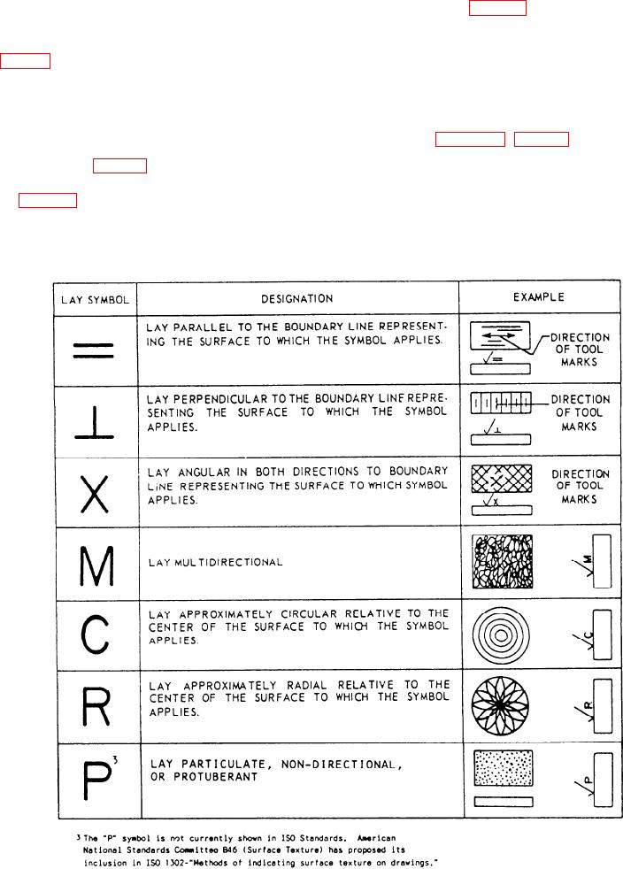
Lay is the direction of the predominant surface
number in the roughness height rating, the smoother
pattern produced by the tool marks. The symbol
the surface.
indicating lay is placed to the right and slightly above
the point of the surface roughness symbol, as shown
Waviness height values are shown directly above
in view F of figure 2-3. (Fig. 2-4 shows the seven
the extension line at the top of the long leg of the basic
symbols that indicate the direction of lay.)
check (view C, fig. 2-3). Waviness width values are
placed to the right of the waviness height values (view
The roughness width value is shown to the right
D, fig. 2-3). Where minimum requirements for
of and parallel to the lay symbol. The roughness
contact or bearing surfaces must be shown, the
width cutoff is placed immediately below the
extension line and to the right of the long leg of the
percentage is placed at the top of the long leg of the
Figure 2-4.--Symbols indicating the direction of lay.
2-4