
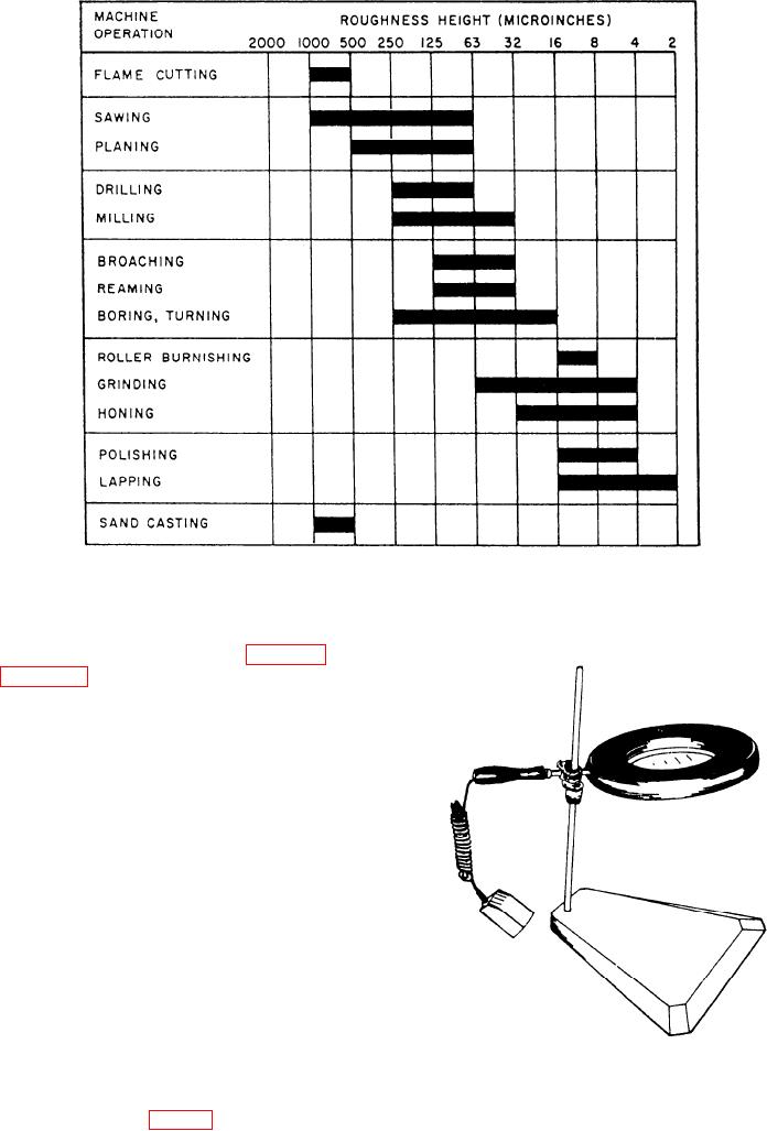
Figure 2-5.--Roughness height values for machine operations.
basic check mark. These symbols for roughness
width are shown in view G and H of figure 2-3.
Figure 2-5 shows a sampling of some roughness
height values that can be obtained by the different
machine operations.
READING SURFACE FINISH QUALITY
A surface finish is seldom flat. We said earlier that
close examination with surface finish measuring
instruments shows the surface to be formed of irregular
waves. On top of the waves are other smaller
irregularities known as peaks and valleys. We will now
discuss several ways to evaluate surface finish.
VISUAL INSPECTION
There are occasions when visual comparison with
the naked eye will show that one surface is rougher
than the other. This is possible only in cases of widely
differing surfaces. You also can use visual inspection
Figure 2-6.--Magnifier with illuminator for surface inspection.
to detect large cracks in metal.
You can make a visual comparison with
illuminated magnifiers (fig. 2-6).
2-5