
installed in a true vertical or horizontal position. This
assumes that the pipe flange holes are also in the
standard location on the pitch circle. Before you do a
valve flange layout job, find out whether the holes are
to be placed in the standard position. If you are
working on a "per sample" job, follow the layout of
the sample.
Assuming you are sure of the size and number of
holes and the radius of the pitch circle, use the
following procedure to set up the layout for straight
globe or gate valve flanges.
1. Fit a fine grain wood plug into the opening in
each flange. (See fig. 2-30.) The plug should fit
snugly and be flush with the face of the flange.
2. Apply layout dye to the flange faces, or, if dye
is not available, rub chalk on the flange faces to make
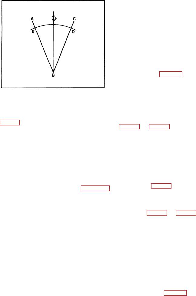
Figure 2-29.--Bisecting an angle.
the drawn lines clearly visible.
3. Locate the center of each flange with a surface
gauge, or use a center head and rule combination if
To bisect an angle, let's assume angle ABC
the flange diameter is relatively small. (See view A,
(fig. 2-29) is given. With B as a center, draw an arc
fig. 2-24 and fig. 2-19.) After you locate the exact
cutting the sides of the angle at D and E. With D and
center point on each flange, mark the center with a
E as centers, and with a radius greater than half of arc
sharp prick-punch.
DE, draw arcs intersecting at F. Then, draw a line
from B through point F to bisect angle ABC.
4. Use dividers to scribe the pitch or bolt circle.
Check to see that the pitch circle and the outside edge
LAYING OUT VALVE FLANGE BOLT
of the flange are concentric.
HOLES
5. Draw the vertical bisector. This line must pass
through the center point of the flange and must be
Before describing the procedure used to make
visually located directly in line with the axis of the
valve flange layouts, we need to clarify the
valve stem (see fig. 2-30).
terminology used in the description. Figure 2-30
shows a valve flange with the bolt holes marked on
6. Draw the horizontal bisector. This line also
the bolt circle. The straight-line distance between the
must pass through the center point of the flange and
centers of two adjacent holes is called the PITCH
must be laid out at a right angle to the vertical
CHORD. The bolt hole circle itself is called the
bisector. (See fig. 2-30 and fig. 2-27.)
PITCH CIRCLE. The vertical line across the face of
Up to this point, the layout is the same for all
the flange is the VERTICAL BISECTOR, and the
flanges regardless of the number of holes. Beyond
horizontal line across the face of the flange is the
this point, however, the layout differs with the number
HORIZONTAL BISECTOR.
of holes. The layout for a 6-hole flange is the simplest
The bolt holes center on the pitch circle and are
one and we'll describe it first.
equal in distance. The pitch chord between any two
adjacent holes is exactly the same as the pitch chord
Six-Hole Flange
between any other two adjacent holes. Note that the
two top holes and the two bottom holes straddle the
Set your dividers exactly to the dimension of the
vertical bisector; the vertical bisector cuts the pitch
pitch circle radius. Place one leg of the dividers on
chord for each pair exactly in half. This is the
the point where the horizontal bisector crosses the
standard method used to place the holes for a 6-hole
pitch circle on the right-hand side of the flange.
flange. In the 4-, 8-, or 12-hole flange, the bolt holes
(Point 1 in view A of figure 2-3 1.) Draw a small arc
straddle both the vertical and horizontal bisectors.
across the pitch circle at points 2 and 6. Next, place
This system of hole placement permits a valve to be
one leg of the dividers at the intersection of the pitch
2-14