
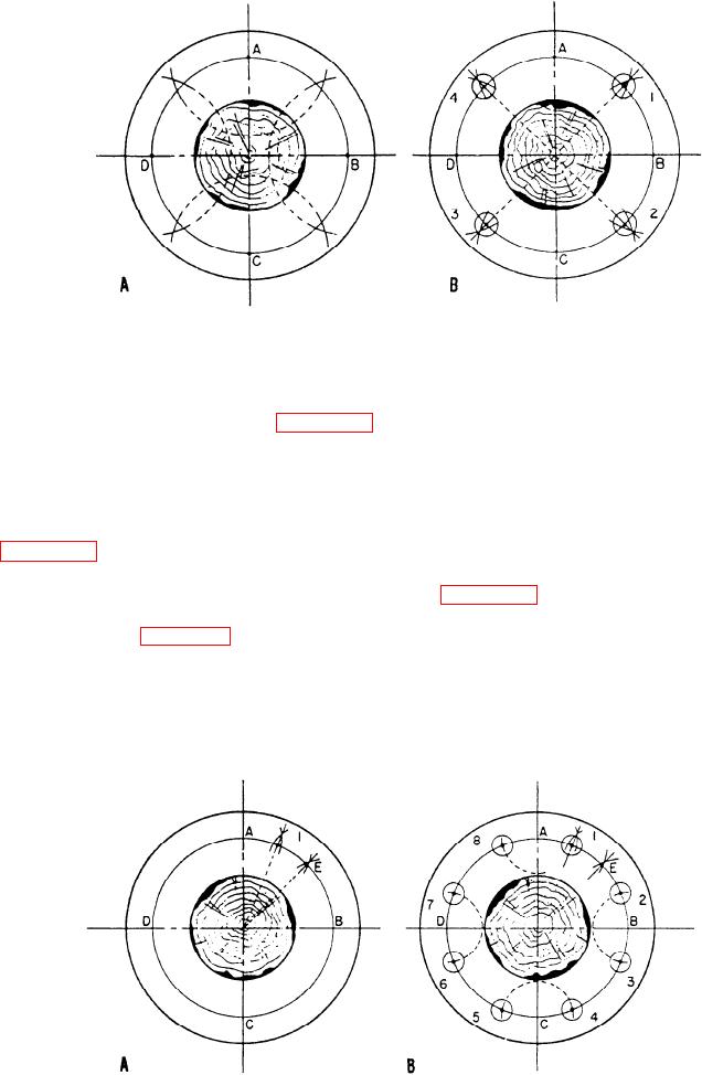
Figure 2-32.--Four-hole flange development.
prick-punch "witness marks" around the
accuracy, set your divider for the pitch between any
circumference, as shown in view B of figure 2-31.
two adjacent holes and step around the pitch circle. If
These witness marks will be cut exactly in half by the
the holes are not evenly spaced, find your error and
drill to verify a correctly located hole.
correct it. When the layout is correct, follow the
center-punching and witness-marking procedures
Four-Hole Flange
described for the 6-hole flange layout.
Figure 2-32 shows the development for a 4-hole
Eight-Hole Flange
flange layout. Set your dividers for slightly more than
half the distance of arc AB. Scribe an intersecting arc
Figure 2-33 shows the development of an 8-hole
across the pitch circle line from points A, B, C, and D,
flange. First locate point E by the same method
as shown in view A of figure 2-32. Next, draw a short
described to locate point 1 in the 4-hole layout. Then,
radial line through the point of intersection of each
divide arc AE in half by the same method. The
pair of arcs as shown in view B. The points where
midpoint of arc AE is the location for the center of the
these lines cross the pitch circle (1, 2, 3, and 4) are the
hole (1). (Set view A of fig. 3-33.) Next, set your
centers for the holes. To check the layout for
dividers for distance A (l), and draw an arc across the
Figure 2-33.--Eight-hole flange development.
2-16