
TM 55-2815-574-24
0097
REMOVAL
WARNING
Remove all jewelry before conducting maintenance. Do not wear watches, rings,
identification tags, or other jewelry which could short across electrical components
or catch on vehicle components. Failure to comply may result in personnel injury or
death.
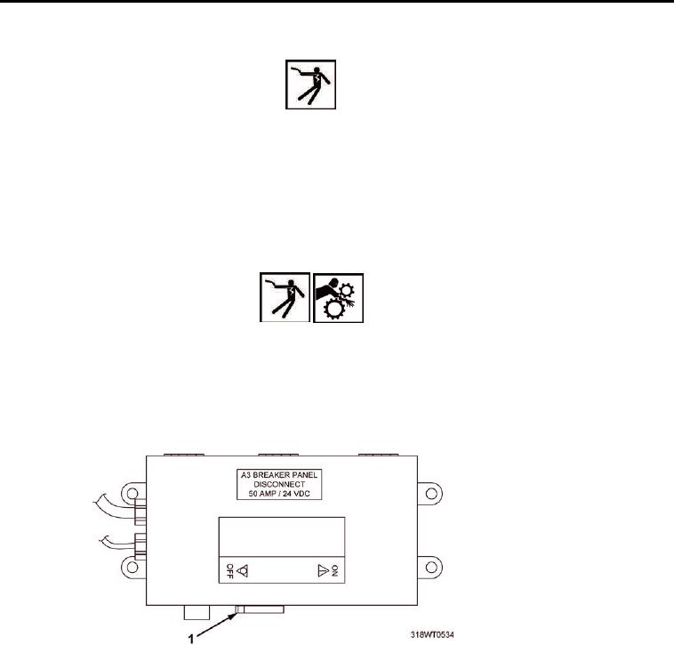
1. Place A3 breaker switch (Figure 1, Item 1), located on A10 panel, in OFF position. Refer to
TM 55-1925-205-10 for breaker location.
WARNING
Before attempting any maintenance, ensure power supply (switches, circuit
breakers, etc..) has been disconnected and locked/tagged out against unauthorized
accidental start-up or else death or serious injury due to electric shock and/or
moving machinery could occur.
2.
Lock Out/Tag Out (LO/TO) A3 breaker switch (Figure 1, Item 1). Refer to FM 4-01.502 for LO/TO
procedure.
Figure 1. A3 Breaker Switch.
3. Remove two hex nuts (Figure 2, Item 1) and capscrews (Figure 2, Item 4) with
lockwashers (Figure 2, Item 5) from rod assembly (Figure 2, Item 6).
4. Remove rod assembly (Figure 2, Item 6) from actuator (Figure 2, Item 2) and
blower (Figure 2, Item 3). Discard rod assembly.
END OF TASK
INSTALLATION
1. Install new rod assembly (Figure 2, Item 6) on actuator (Figure 2, Item 2) and
blower (Figure 2, Item 3).
2. Install two capscrews (Figure 2, Item 4) with lockwashers (Figure 2, Item 5) and
hex nuts (Figure 2, Item 1) on rod assembly (Figure 2, Item 6).
3. Tighten hex nuts (Figure 2, Item 1).