
TM 55-2815-574-24
FIELD MAINTENANCE
ENGINE
FUEL PRIMING PUMP REPLACEMENT
INITIAL SETUP:
Tools and Special Tools
Personnel Required
General mechanic's tool kit
Engineer 88L
(WP 0179, Table 1, Item 130)
Chemical gloves (WP 0179, Table 1, Item 52)
References
Drain pan (WP 0179, Table 1, Item 87)
FM 4-01.502
Industrial goggles (WP 0179, Table 1, Item 54)
TM 55-1925-205-10
Utility apron (WP 0179, Table 1, Item 8)
Materials/Parts
Equipment Condition
Antiseizing tape (WP 0178, Table 1, Item 37)
Engine cool to touch
Hazardous material spill clean-up kit
Propulsion module ventilated
(WP 0178, Table 1, Item 34)
(TM 55-1925-205-23)
Marker tags, with metal eyelet patch Qty: 2
(WP 0178, Table 1, Item 36)
REMOVAL
1.
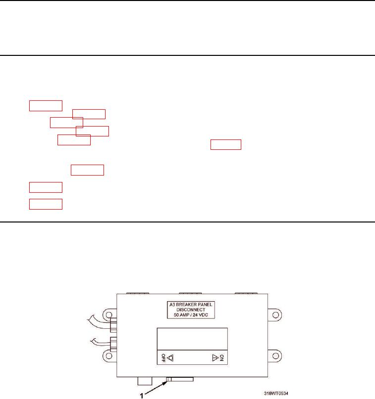
Place A3 breaker switch (Figure 1, Item 1), located on A10 panel, in OFF position. Refer to
TM 55-1925-205-10 for breaker location.
2.
Lock Out/Tag Out (LO/TO) A3 breaker switch (Figure 1, Item 1). Refer to FM 4-01.502 for LO/TO procedure.
Figure 1. A3 Breaker Switch.