TM 55-2815-574-24
0095
ASSEMBLY - Continued
c.
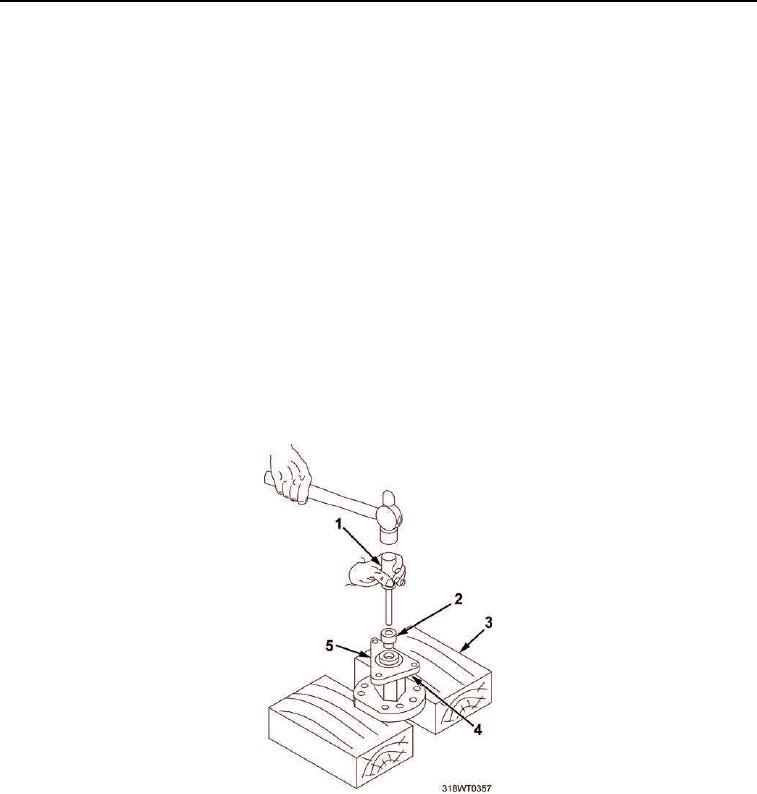
Insert pilot of installer handle (Figure 9, Item 1) in fuel pump body (Figure 9, Item 3) aligning oil seal
(Figure 9, Item 2) with fuel pump body flange so that oil seal starts straight.
d.
Use hammer to drive oil seal (Figure 9, Item 2) into fuel pump body (Figure 9, Item 3) until it bottoms
out.
e.
Ensure fuel pump body (Figure 9, Item 4) sits flush on wedge wood (Figure 9, Item 3).
f.
Place shorter end of adaptor (Figure 9, Item 2) over pilot and against shoulder of the installer handle
(Figure 9, Item 1).
g.
Align new outer oil seal (Figure 9, Item 5) on pilot of installer handle (Figure 9, Item 1) so that lip of the
oil seal (Figure 9, Item 5) faces adaptor (Figure 9, Item 2).
h.
Insert pilot of installer handle (Figure 9, Item 1) in fuel pump body (Figure 9, Item 4) aligning oil seal
(Figure 9, Item 5) with fuel pump body flange so that oil seal starts straight.
NOTE
Oil seals will be positioned so that space between them will correspond with drain
holes located in bottom of fuel pump body.
i.
Use hammer to drive oil seal (Figure 9, Item 5) into fuel pump body (Figure 9, Item 4) until it is flush
with gasket surface.
Figure 9. Oil Seal Installation with Installer and Adapter.
3.
Install relief valve (Figure 10, Item 2), valve spring (Figure 10, Item 5), pin (Figure 10, Item 3), new copper
gasket (Figure 10, Item 5) and relief valve plug (Figure 10, Item 6) into valve cavity of fuel pump body
(Figure 10, Item 1) by performing the following:
a.
Secure fuel pump body (Figure 10, Item 1) in a bench vise, equipped with soft jaws, with relief valve
cavity facing up.
b.
Lubricate outside diameter of relief valve (Figure 10, Item 2), with a light coat of lubricating oil.

