
TM 55-2815-574-24
0095
DISASSEMBLY - Continued
10.
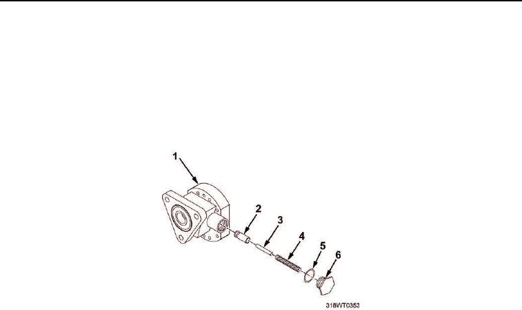
Remove relief valve plug (Figure 5, Item 6) and copper gasket (Figure 5, Item 5) from fuel pump body
(Figure 5, Item 1). Discard gasket.
11.
Remove valve spring (Figure 5, Item 4), pin (Figure 5, Item 3) and relief valve (Figure 5, Item 2) from in fuel
pump body (Figure 5, Item 1).
12.
Remove fuel pump body (Figure 5, Item 1) from holding fixture.
13.
Remove holding fixture from bench vise.
Figure 5. Relief Valve Plug Disassembly.
14.
Secure fuel pump body (Figure 6, Item 2) in bench vise at a side angle.
15.
Remove inner and outer oil seal (Figure 6, Items 3 and 4) from fuel pump body (Figure 6, Item 2) using oil
seal remover tool (Figure 6, Item 1).
NOTE
Observe position of the oil seal lips before oil seals are removed to permit installation
of new seals in same position.
a.
Tap end of oil seal remover tool (Figure 6, Item 1) with a hammer to remove seal (Figure 6, Item 3).
b.
Tap end of oil seal remover tool (Figure 6, Item 1) with a hammer to remove seal (Figure 6, Item 4).
c.
Discard oil seals (Figure 6, Items 3 and 4).
16.
Remove fuel pump body (Figure 6, Item 2) from bench vise.