
TM 55-2815-574-24
0095
DISASSEMBLY - Continued
2.
Install fuel pump (Figure 2, Item 1) on holding fixture (Figure 2, Item 4) from fuel pump tool set.
3.
Secure holding fixture (Figure 2, Item 4) in a bench vise (Figure 2, Item 5) .
4.
Remove inlet port elbow (Figure 2, Item 2) and outlet port elbow (Figure 2, Item 3) from fuel pump
(Figure 2, Item 1).
Figure 2. Fuel Pump Secured in Vise.
5.
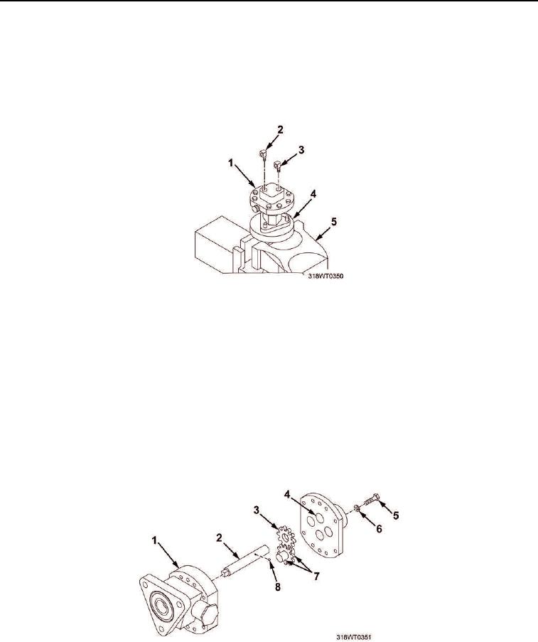
Remove eight cap screws (Figure 3, Item 5) and lock washers (Figure 3, Item 6) from fuel pump cover
(Figure 3, Item 4).
6.
Remove fuel pump cover (Figure 3, Item 4) from the fuel pump body (Figure 3, Item 1).
NOTE
Do not remove driven gear from driven shaft. The driven shaft and driven gear are serviced
as an assembly.
7.
Remove driveshaft (Figure 3, Item 2), drive gear (Figure 3, Item 3) and the gear retaining ball
(Figure 3, Item 8) as an assembly from the fuel pump body (Figure 3, Item 1).
8.
Remove gear (Figure 3, Item 7) from fuel pump body (Figure 3, Item 1).
Figure 3. Fuel Pump Cover and Drive Gear Disassembly.