
TM 55-2815-574-24
0094
REMOVAL
WARNING
Remove all jewelry before conducting maintenance. Do not wear watches, rings,
identification tags, or other jewelry which could short across electrical components or catch
on vehicle components. Failure to comply may result in personnel injury or death.
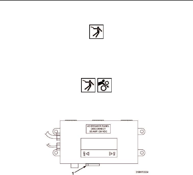
1.
Place A3 breaker switch (Figure 1, Item 1), located on A10 panel, in OFF position. Refer to
TM 55-1925-205-10 for breaker location.
WARNING
Before attempting any maintenance, ensure power supply (switches, circuit breakers, etc..)
has been disconnected and locked/tagged out against unauthorized accidental start-up or
else death or serious injury due to electric shock and/or moving machinery could occur.
2.
Lock Out/Tag Out (LO/TO) A3 breaker switch (Figure 1, Item 1). Refer to FM 4-01.502 for LO/TO procedure.
Figure 1. A3 Breaker Switch.
3.
Verify fuel supply and return valves (Figure 2, Item 1) are closed.