
TM 55-2815-574-24
0093
ADJUST INJECTOR RACK CONTROL LEVER - Continued
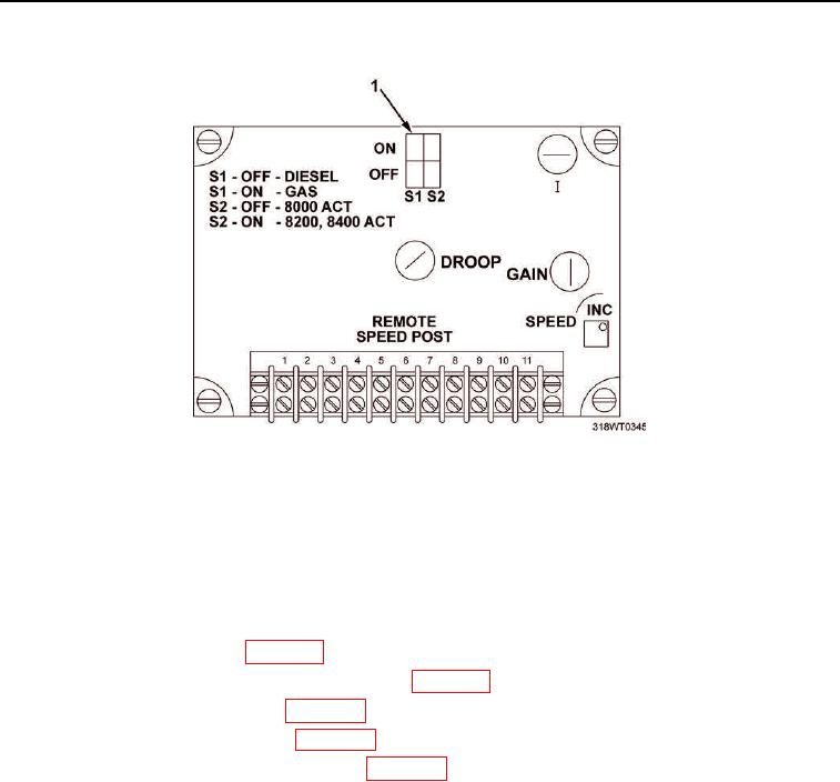
Figure 11. S1 Switch
47.
The second engineer repeats Step 22, (a and b). If the injector racks do not return to the original position,
the adjustment procedure must be repeated from Step 1.
END OF TASK
FOLLOW-ON MAINTENANCE
1.
Adjust electronic governor (WP 0097).
2.
Install cylinder head poppet valve rockers covers (WP 0044).
3.
Install emergency stop solenoid (WP 0170).
4.
Install air inlet collector assembly (WP 0104).
5.
Install crankcase breather limiter assembly (WP 0106).
6.
Install powered section engine hatch (TM 55-1925-205-23).
7.
Install operator's cab (TM 55-1925-205-23).
8.
Install exhaust plenum (TM 55-1925-205-23).
9.
Install intake plenum assembly (TM 55-1925-205-23).
10.
Install main navigation mast (TM 55-1925-205-23).
11.
Install SINCGARS antenna (TM 11-5820-890-10-8).
12.
Perform operational checks (TM 55-1925-205-10).
END OF TASK
END OF WORK PACKAGE