
TM 55-2815-574-24
FIELD MAINTENANCE
ENGINE
CRANKCASE BREATHER LIMITER ASSEMBLY REPLACEMENT
INITIAL SETUP:
Tools and Special Tools
References
General mechanic's tool kit
TM 55-1925-205-10
(WP 0179, Table 1, Item 130)
Personnel Required
Engineer 88L
REMOVAL
NOTE
The following procedure is typical for removal and installation of limiter assemblies on
both sides.
1.
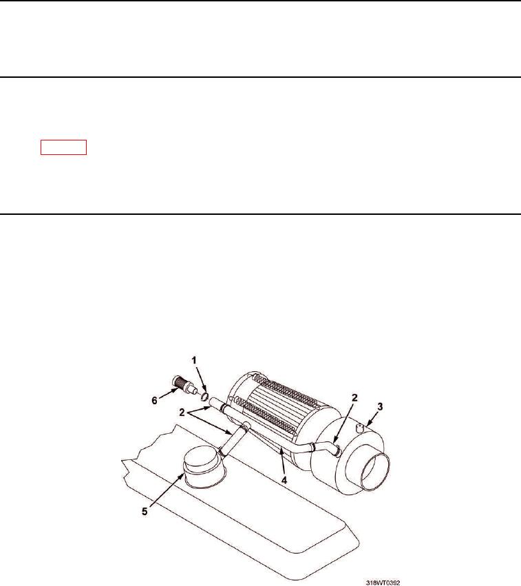
Loosen six clamps (Figure 1, Item 1) connecting limiter assembly (Figure 1, Item 6), three hose assemblies
(Figure 1, Item 2), and tube (Figure 1, Item 4), to air inlet collector (Figure 1, Item 3) and crankcase breather
(Figure 1, Item 5).
Figure 1. Limiter Assembly.
2.
Remove limiter assembly (Figure 1, Item 6). Discard limiter assembly.
3.
Disconnect two hoses (Figure 1, Item 2) from air inlet collector (Figure 1, Item 3) and crankcase breather
(Figure 1, Item 5).
4.
Remove three hoses (Figure 1, Item 2) from tube (Figure 1, Item 4).