
TM 55-2815-574-24
0107
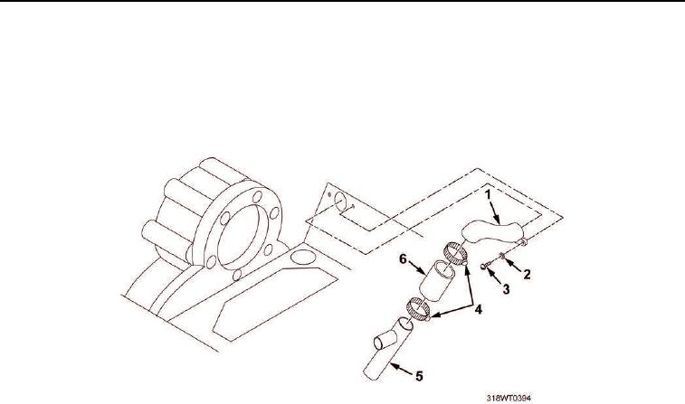
INSTALLATION
1.
Install pipe (Figure 2, Item 5), elbow (Figure 2, Item 1), and hose (Figure 2, Item 6) as an assembly on
engine.
2.
Install two screws (Figure 2, Item 3) and new lockwashers (Figure 2, Item 2) on elbow (Figure 2, Item 1).
3.
Install two hose clamps (Figure 2, Item 4) on hose (Figure 2, Item 6).
Figure 2. Crankcase Breather Hose Elbow.
4.
Install hose (Figure 1, Item 4) on pipe (Figure 1, Item 5).
5.
Install pipe (Figure 1, Item 5) and hose (Figure 1, Item 4) as an assembly on engine.
6.
Install two hose clamps (Figure 1, Item 3) on hose (Figure 1, Item 4).
7.
Install two screws (Figure 1, Item 2) and new lockwashers (Figure 1, Item 1) on pipe (Figure 1, Item 5).
END OF TASK