
TM 55-2815-574-24
0093
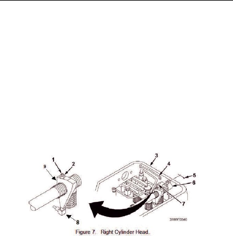
ADJUST INJECTOR RACK CONTROL LEVER - Continued
14.
Disconnect the fuel rod (Figure 6, Item 1) from the clevis lever (Figure 6, Item 4).
15.
On the right cylinder bank (Figure 7, Item 3), install the fuel rod (Figure 7, Item 4) in the clevis lever
(Figure 7, Item 6).
16.
Install the clevis pin (Figure 7, Item 7) through the clevis lever (Figure 7, Item 6).
17.
Install the cotter pin (Figure 7, Item 5) through the clevis pin (Figure 7, Item 7).
NOTE
The full fuel position is reached when the injector lever is completely in the injector rack.
18.
The first soldier pulls the throttle control arm (Figure 4, Item 1) to the full fuel position and holds the control
arm with light pressure.
CAUTION
Do not overtighten injector rack control lever adjusting screws. Failure to comply may result
in damage to injector rack control tube.
19.
The second soldier then tightens the adjusting screw (Figure 7, Item 1) of the right cylinder bank
(Figure 7, Item 3), until the injector rack (Figure 7, Item 8) starts to rotate slightly, or until increased
resistance is felt.