
TM 55-2815-574-24
0093
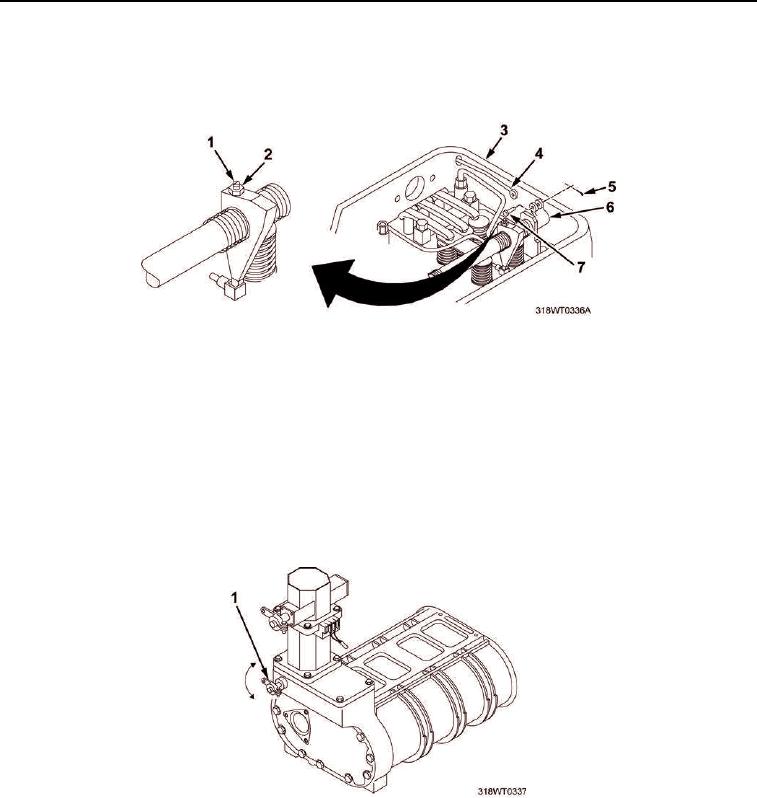
ADJUST INJECTOR RACK CONTROL LEVER - Continued
On the right cylinder bank (Figure 3, Item 3), remove cotter pin (Figure 3, Item 5) and clevis pin
3.
(Figure 3, Item 7).
Figure 3. Right Cylinder Head.
Disconnect fuel rod (Figure 3, Item 4) from clevis lever (Figure 3, Item 6).
4.
Loosen four lock nuts (Figure 3, Item 2) and screws (Figure 3, Item 1) on the injectors of the right cylinder
5.
bank (Figure 3, Item 3).
NOTE
The full fuel position is reached when the injector rack is completely in.
6.
The first engineer pulls the throttle control arm (Figure 4, Item 1) to the full fuel position and holds the
control arm with light pressure.
Figure 4. Throttle Control Arm.