
TM 55-2815-574-24
0095
DISASSEMBLY - Continued
9.
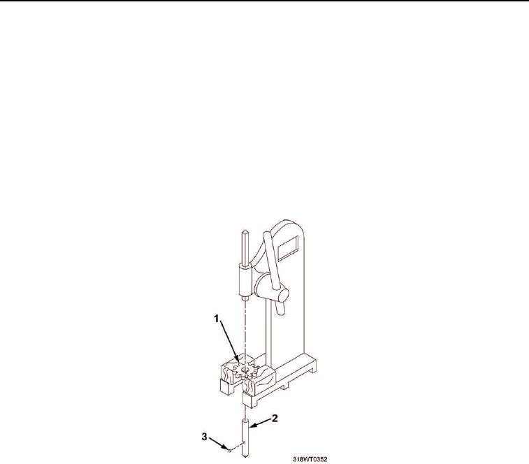
Disassemble driveshaft (Figure 4, Item 2), drive gear (Figure 4, Item 1) and gear retaining ball
(Figure 4, Item 3) assembly.
CAUTION
Do not press squared end of the shaft through gear. Failure to comply may result in
damage to equipment.
a.
Press driveshaft (Figure 4, Item 2) inward just far enough to remove gear retaining ball
(Figure 4, Item 3).
b.
Remove gear retaining ball (Figure 4, Item 3).
c.
Invert driveshaft and gear assembly and press driveshaft (Figure 4, Item 2) from drive gear
(Figure 4, Item 1).
Figure 4. Driveshaft, Drive Gear and Retaining Ball Disassembly.