TM 55-2815-574-24
0095
ASSEMBLY - Continued
CAUTION
Driven gear must be centered on driven shaft to give proper end clearance and
chamfered end of gear teeth of the production gear, must face fuel pump body. Failure
to comply may result in damage to equipment.
NOTE
If a service replacement gear with a slot is used, slot must face toward fuel pump
cover.
a.
Use lubricating oil to lubricate gear assembly (Figure 13, Item 7).
b.
Install gear in pump body (Figure 13, Item 6).
10.
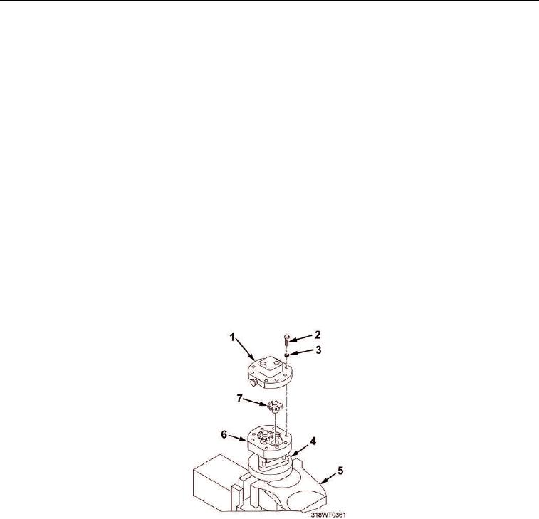
Install fuel pump cover (Figure 13, Item 1) on fuel pump body (Figure 13, Item 6).
a.
Apply a thin coat of adhesive sealant on face of fuel pump cover (Figure 13, Item 1) outside of gear
pocket area.
b.
Align fuel pump cover (Figure 13, Item 1) with two dowel pins on fuel pump body (Figure 13, Item 6).
c.
Install fuel pump cover (Figure 13, Item 1) on fuel pump body (Figure 13, Item 6).
d.
Install eight bolts (Figure 13, Item 2) and lock washers (Figure 13, Item 3) to secure fuel pump cover
(Figure 13, Item 1) to fuel pump body (Figure 13, Item 6). Tighten bolts alternately and evenly.
Figure 13. Gear Assembly Installation.
CAUTION
Do not coat first two threads of fittings with sealing compound. Failure to comply may result
in damage to equipment.
11.
Avoiding first two threads, apply a thin coat of non-hardening sealant to threads of inlet port
(Figure 14, Item 2) and outlet port (Figure 14, Item 3) elbows.
12.
Install inlet port (Figure 14, Item 2) and outlet port (Figure 14, Item 3) elbows onto the replacement fuel
pump (Figure 14, Item 1).

