
TM 55-2815-574-24
0072
INSTALLATION - Continued
NOTE
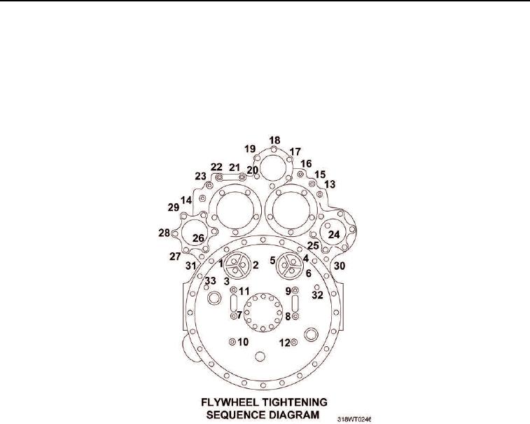
The tightening sequence is different from the torquing sequence. The two different
sequences must be followed for the flywheel housing to align properly.
35.
Use flywheel housing tightening sequence diagram (Figure 25) to snug all mounting bolts in the specified
order.
Figure 25.
36.
Use torque wrench and a torque sequence diagram to torque the first six cap screws in flywheel housing to
90 to 100 ft lb (122 to 136 Nm).
37.
Use torque wrench and socket set to torque the seventh through ninth cap screws to 480 to 540 in-lb
(54 to 61 Nm).
38.
While one soldier turns the crankshaft screw (Figure 26, Item 55) clockwise the other soldier, use torque
wrench, socket set, and a torque sequence diagram to torque the tenth through twelfth cap screws to
480 to 540 in-lb (54 to 61 Nm).
39.
Use torque wrench and a torque sequence diagram (Figure 26) to torque the thirteenth through twenty
seventh cap screws to 25 to 30 ft lb (34 to 41 Nm).