• Home
  • Download PDF
  • Order CD-ROM
  • Order in Print
Install new cap screw (Figure 16, Item 1) into access hole.
Install access plate (Figure 19, Item 4) on flywheel housing (Figure 19, Item 1).

TECHNICAL MANUAL FIELD AND SUSTAINMENT MAINTENANCE MANUAL FOR ENGINE 8V92TA
Page Navigation
  367    368    369    370    371  372  373    374    375    376    377  
img
.
TM 55-2815-574-24
0072
INSTALLATION - Continued
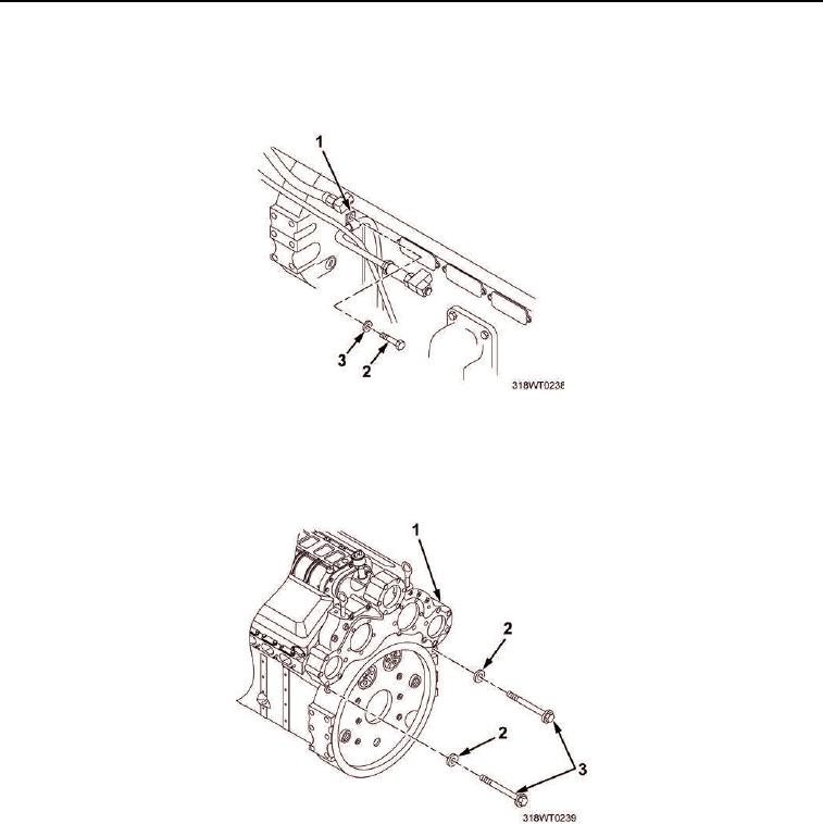
14.
Install cap screw (Figure 17, Item 2) and washer (Figure 17, Item 3) through air box drain retaining clip
(Figure 17, Item 1).
Figure 17.
15.
Install two new cap screws (Figure 18, Item 3) and new lockwashers (Figure 18, Item 2) into flywheel
housing (Figure 18, Item 1).
Figure 18.
0072-14


Privacy Statement
Press Release
Contact

© Copyright Integrated Publishing, Inc.. All Rights Reserved.