
TM 55-2815-574-24
0072
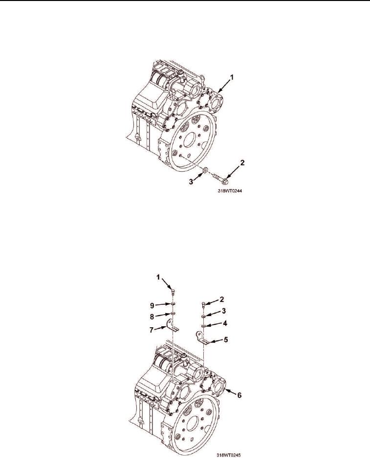
INSTALLATION - Continued
32.
Install six new cap screws (Figure 23, Item 2) and new lockwashers (Figure 23, Item 3) into flywheel
housing (Figure 23, Item 1).
Figure 23.
33.
Install two cap screws (Figure 24, Item 1), new lockwashers (Figure 24, Item 9), flat washers
(Figure 24, Item 8) and left bank bracket (Figure 24, Item 7) on flywheel housing (Figure 24, Item 6).
34.
Install two cap screws (Figure 24, Item 2), lockwashers (Figure 24, Item 3), flat washers (Figure 24, Item 4)
and right bank bracket (Figure 24, Item 5) on flywheel housing (Figure 24, Item 6).
Figure 24.